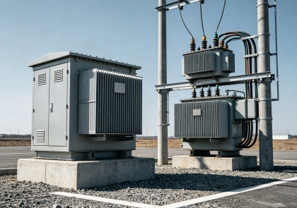
Transformer is an indispensable electrical equipment in daily life, widely used in power plants, substations and families, its core function is to transfer power through electromagnetic induction, voltage regulation, to meet the needs of various types of electricity.
Understanding of its main components can help master the working principle, but also for operation and maintenance troubleshooting to provide a basis for this article will be a detailed dismantling of the core of the transformer and auxiliary components, to explain its role, type and importance.
Transformer Core
Iron core is one of the core components of the transformer, its core role is to achieve the magnetic coupling between the windings, to provide a low reluctance path for the magnetic field, while minimizing eddy current loss and hysteresis loss, to ensure the efficiency of power transmission. Simply put, the core acts as a “conduit” for the transformer’s magnetic field, allowing the electromagnetic induction process to occur efficiently and steadily.
The core consists of two key subassemblies: the core posts (also known as core legs) and the yoke. The core posts are the vertically oriented portion of the core on which the transformer’s coils (windings) are wrapped, and in some designs may be located on the outside of the outermost coils.
The yoke is a horizontally distributed part, which connects the core posts into a closed whole, forming a complete magnetic field circuit to ensure that the magnetic flux can circulate smoothly and avoid the energy loss caused by magnetic field leakage.
Iron core material is usually selected iron, steel and other ferromagnetic materials, this kind of material has good magnetic conductivity, can effectively enhance the magnetic field strength, improve the transformer’s energy transfer efficiency, is the core to realize its core function of the foundation.
Transformer Windings
Winding is the core component of the transformer to achieve voltage conversion, essentially made of copper or aluminum coil, its main role is to determine the size of the output voltage through the principle of electromagnetic induction, and to achieve the voltage step-up or step-down. Copper and aluminum have excellent electrical conductivity and low electrical resistance, which reduces the heat loss that occurs when current passes through them, making them ideal materials for making windings.
Primary Winding
Primary winding is the input winding, directly connected to the power supply, responsible for receiving power from the grid or other circuits, the winding is usually equipped with a voltage regulating tap, when the input voltage and the rated voltage of the transformer there is a slight deviation, can be adjusted through the tap to adapt to the input voltage, to ensure that the equipment operates normally.
Secondary Winding
The secondary winding is the output winding, which is responsible for delivering the power converted by electromagnetic induction to the loads, such as the production equipment in factories, the electric facilities in commercial buildings and various electric appliances in the family. In the case of step-down transformers, the secondary winding has a lower voltage and is therefore usually placed close to the core, requires a relatively low level of insulation, and is connected to the secondary bushing of the transformer by cables or busbars.
Primary vs. Secondary Windings
The core difference between the primary winding and the secondary winding lies in the connection mode and functional positioning: the primary winding is connected to the input power supply, which is the “receiving end” of the electric energy; the secondary winding is connected to the load, which is the “output end” of the electric energy; the two of them are close to each other, but they are not directly connected to each other electrically, relying entirely on the magnetic field transmitted by the iron core to realize the power of the transformer. Relying on the magnetic field transmitted by the iron core to realize the energy coupling.
How Transformer Windings Work
The principle of operation of the winding is based on Faraday’s law of electromagnetic induction:
When an alternating current passes through the primary winding, a varying magnetic field is generated in the core, which passes through the secondary winding and induces an induced voltage in the secondary winding. The magnitude of the induced voltage is determined by the turns ratio of the two windings, which is the principle of turns ratio of a transformer. The voltage ratio is equal to the turns ratio, while the current ratio is inversely proportional to the turns ratio.
For example, if the primary winding has 100 turns and the secondary winding has 50 turns, then the output voltage of the transformer will be half of the input voltage, which belongs to the step-down transformer; if the number of turns of the secondary winding is more than that of the primary winding, it will realize the step-up function. This voltage conversion without mechanical movement makes the transformer an efficient and reliable energy transfer device in the power system.
Transformer Insulation
Insulation is an indispensable auxiliary component of the transformer, and its core role is to isolate the electrical components of different potentials, prevent the occurrence of short-circuit accidents, and at the same time to enhance the safety of the equipment, to extend the service life of the transformer, and to ensure that the efficiency of the transmission of electrical energy is not affected. Without good insulation protection, the transformer winding, core and other components are very easy to leakage, short circuit, which leads to equipment damage or even cause safety accidents.
Materials & Their Properties
Transformer insulation materials are varied, the performance of different materials and applicable scenarios are different, the common main categories are as follows:
- Cellulose-based materials (kraft paper, pressed cardboard) is one of the most commonly used insulating materials, has a low cost, wide range of sources, processing convenience and other advantages, widely used in all types of transformer insulation protection, but this type of material is more sensitive to moisture, if not properly maintained, moisture intrusion will significantly shorten its service life, affecting the insulation effect.
- Heat-resistant upgraded cellulose is a chemically treated cellulose material that can withstand higher working temperatures and has better anti-aging properties than ordinary kraft paper, which is suitable for transformers with higher working ambient temperatures or higher service life requirements, and can prolong the equipment’s operating life under the same load conditions.
- Aramid fiber (Nomex®) has excellent heat resistance and mechanical strength. Although relatively high in cost, it excels in high-stress and demanding application scenarios, making it an ideal choice for high-end transformer insulation, which can effectively safeguard the stable operation of the equipment under harsh conditions.
- In addition to solid insulating materials, insulating liquid is also an important part of the transformer insulation system: mineral oil is the traditional insulating liquid, with excellent dielectric properties and cost advantages, widely used, but the environmental protection is relatively poor;
- Ester (natural or synthetic) insulating liquid is environmentally friendly, high ignition point, good humidity resistance, etc., in recent years in renewable energy and urban power facilities are more and more widely used; silicone oil belongs to the special insulating liquid, suitable for high temperature environment, strong stability, but the cost is higher.
The quality of the insulation device directly affects the service life of the transformer, operational efficiency and safety: high-quality insulation materials can effectively isolate the moisture, impurities and other external factors, reduce the wear and tear of the internal components and aging, reduce the energy leakage, and at the same time to avoid short-circuit, leakage and other safety hazards for the long-term stable operation of the transformer to provide protection.
Transformer Cooling Parts
Transformer in the process of operation, due to the current through the winding heat loss, the core of the hysteresis loss and eddy current loss, will continue to produce heat. If the heat can not be emitted in a timely manner, the internal temperature of the equipment will rise sharply, which will lead to accelerated aging of the insulation material, reduced operating efficiency, and in serious cases, it will also lead to equipment failure or even burnt out. Therefore, the core role of the cooling system is to disseminate the heat generated during the operation of the transformer in a timely manner, to maintain the normal operating temperature of the equipment, to ensure the safe and efficient operation of the equipment.
Cooling Method
According to the capacity of the transformer, the use of the scene and work requirements, there are two common cooling methods:
- Oil-cooled modeis the mainstream cooling mode of large transformers, through the insulating oil circulation flow away from the internal heat of the equipment, heat dissipation effect is excellent, can effectively extend the service life of the equipment, widely used in power plants, power grids in the large-scale power transformers and industrial transformers with high requirements for efficiency.
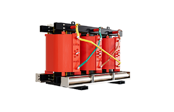
- Air-cooled modehas the advantages of easy maintenance, environmental protection and no pollution, there is no risk of oil leakage, suitable for small and medium-sized distribution transformers, such as urban buildings, hospitals, office buildings, tunnels and other high safety requirements and limited space scenes, to meet the cooling needs of transformers in such scenes.
Transformer Tap Changer
The tap changer is a key auxiliary component used to regulate the voltage ratio of the transformer, and its core role is to adjust the turns ratio between the primary and secondary windings by changing the effective number of turns of the windings, so as to maintain the output voltage within the specified range. In the actual power system, the grid voltage may change due to load fluctuations, transmission distance and other factors, and the tap changer is able to adapt to such changes in a timely manner to ensure the stability of the output voltage and to meet the load’s power needs.
Types of Transformer Tap Changers
There are two main types of on-load tap-changers depending on the operating conditions:
De-energized Tap Changers
De-energized tap changers (DETCs), also known as off-line tap changers, can only be used for voltage regulation when the transformer is out of service and the power supply is cut off. These tap changers are simple and inexpensive, with low maintenance requirements, but they are unable to cope with real-time load fluctuations and are mainly used in distribution networks where voltage regulation does not need to be carried out frequently.
The core components include a selector switch for selecting the tap, a mechanical link for connecting the windings and an indicator for the tap position, which is easy to operate and highly reliable.
Load Tap Changers (OLTC)
Load Tap Changers (OLTC) are indispensable components of power distribution systems and voltage regulators because they allow voltage regulation without interrupting the power supply when the transformer is operated under load, and they respond in real time to variations in grid voltage and load.
Its main components include the diverter switch that temporarily carries the current during tap-changeover, the selector switch that selects the new tap position, and the mechanical or electric mechanism that drives the switching action. The structure is relatively complex, but the regulation accuracy and response speed are higher.
Transformer Bushings
The core components of the transformer (such as windings) are usually encapsulated inside the metal shell (tank), and the core role of the bushing is to provide a safe current channel between the internal components and the external electrical system, to guide the internal high voltage current to the external circuit, and at the same time to isolate the high voltage from the transformer shell, to prevent the leakage of current, arc discharge and other faults, and to ensure the safe operation of the transformer.
What do Transformer Bushings Do?
From the structural point of view, the casing is like a protective tube, the internal wrapped with conductive body (usually copper or aluminum, this kind of material has good conductivity and low resistance, which can ensure that the current passes through smoothly), covered with multi-layer insulating material on the outside, to form an effective insulating barrier to avoid the impact of high voltage on the equipment casing and the surrounding environment.
Types of Transformer Bushings
According to the different insulating materials, casing is mainly divided into three categories:
- Oil-impregnated paper casing (OIP) is the traditional type of casing, which adopts oil-impregnated paper as insulating material with excellent insulating performance, has a long history of application and mature maintenance process, and is widely used in various types of oil-immersed transformers;
- Resin impregnated paper casing (RIP) belongs to the dry type design, using resin impregnated paper as insulation material, with the advantages of small volume, high space utilization, convenient transportation and installation, etc. It is suitable for the scenarios that have requirements for space and need oil-free insulation;
- Resin-impregnated synthetic (RIS) sleeving, on the other hand, adopts synthetic materials as the insulating core, and has good humidity resistance to adapt to environments with high humidity and susceptible to surface deposits, making it suitable for a wide variety of scenarios.
In addition to insulation materials, sleeving can also be categorized into porcelain sleeving and polymer/silicone rubber sleeving according to the shell material:
- Porcelain casing as the traditional casing shell material, with high mechanical strength, excellent UV resistance, suitable for all kinds of conventional installation scenarios, practicality;
- Polymer / silicone rubber casing is lightweight, good hydrophobicity, can adapt to salt spray, pollution, frequent humidity and other harsh environments, in coastal areas, chemical parks and other scenarios are widely used.
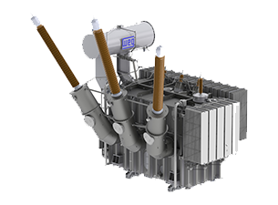
Transformer Tank
The oil tank is the external shell of the transformer, the main role is to accommodate and protect the internal core components (such as iron core, winding), while storing the insulating oil, while the insulating oil is assuming a double role. On the one hand, it provides insulation protection for the internal components to prevent short-circuit accidents;
On the other hand, it carries away the heat generated by the operation of the equipment through its own circulation and assists in heat dissipation. In addition, the oil tank can also isolate the external moisture, dust, impurities and other environmental factors, to avoid internal components erosion, to protect the long-term stable operation of the transformer.
Types of Transformer Tanks
According to the different structure and function, the oil tank is mainly divided into two types:
Conventional Transformer Tank
Conventional sealed tank is a fully enclosed structure, filled with insulating oil inside, equipped with silicone breather for filtering moisture in the air, preventing moisture from entering the tank to contaminate the insulating oil.
This kind of tank is simple in structure, high in reliability, able to withstand the expansion and contraction of oil volume caused by temperature change during the operation of transformer, mainly used in distribution transformer and small and medium-sized power transformer.
Conservator Tank
The conservator tank tank is connected to an independent oil storage container (oil storage cabinet) outside the main oil tank, and its core function is to adapt to the volume change of insulating oil. When the transformer’s operating temperature rises and the insulating oil expands, the excess oil flows into the oil conservator;
When the temperature decreases and the oil volume contracts, the oil in the oil conservator flows back into the main tank. This design can avoid the oil in the main tank directly contact with the air, reduce the moisture and oxygen pollution of the insulating oil, prolong the service life of the insulating oil and the transformer, mainly used in large power transformers, which have higher requirements for the oil quality and operational stability.
Transformer Tank Materials
The material of oil tank is mainly selected according to the application environment and requirements:
Ordinary carbon steel is the most commonly used material, with low cost, high strength, easy to process the advantages, usually through the coating or painting treatment to prevent rust and corrosion, suitable for most outdoor and conventional scenes;
Stainless steel has excellent corrosion resistance, suitable for harsh environments, such as coastal areas, chemical industry, etc., can reduce the environmental factors on the erosion of the tank, reduce maintenance costs; in some special design, will also be used in galvanized steel or aluminum, in order to enhance corrosion resistance or reduce the weight of the tank, but the application of the tank is relatively small.
Transformer Protection
Transformer in the process of long-term operation, may be due to internal faults, such as short circuit, insulation aging, external factors, such as voltage fluctuations, overload and other abnormalities, the core role of the protection system is to detect these anomalies and faults in a timely manner, send out alarms and take corresponding protective measures (such as cutting off power), minimize the fault on the damage to the equipment to prevent the expansion of faults caused by catastrophic Accident, to protect the safety of equipment and personnel.
Transformer protection system has many kinds, designed for different types of faults, mainly including the following kinds:
Overcurrent Protection
Overcurrent protection is mainly used to cope with line short-circuit, equipment overload and other faults, when the current exceeds the rated value, the current is cut off through fuses, circuit breakers, relays and other equipment, to prevent the current from being too large and leading to winding burnout and equipment damage. This type of protection equipment can not solve the root cause of overcurrent, but can quickly cut off the circuit to avoid the expansion of the fault.
Overheating Protection
Overheating protection is used to monitor the operating temperature of the transformer, most of the transformer’s safe operation of the maximum temperature of about 95 ℃, when the temperature is close to or over this limit, overheating protection system will issue an alarm, and automatically cut off the power supply, to prevent accelerated aging of the insulation material, winding burned. Fiber optic sensors are usually used to monitor the core temperature (the core is the highest temperature part inside the transformer) to ensure the accuracy of the monitoring.
Over-Fluxing Protection
Over-Fluxing Protection is used to prevent the excitation current of the transformer from exceeding the safety limit, which can lead to overheating of the equipment when the magnetic flux density is too high, and then cause internal failure. The overexcitation protection system monitors the magnetic flux density in real time, and when it reaches a dangerous level, it triggers the circuit breaker to trip and cut off the power supply to protect the equipment.
Protective Systems on Transformers
Gas detection protection is divided into slow gas detection and fast gas detection, which is used to monitor the gas generated when the insulating oil and insulating materials are aging and failing:
Slow Gas Monitoring Device
slow gas detection mainly monitors the long-term accumulation of gas, monitors the gas pressure through the diaphragm chamber on the top of the tank, and sends out an alarm when the pressure reaches a certain value and records the exhaust frequency, which is used for judging the long-term operation status of the equipment;
Fast Gas Monitoring Device
Fast gas detection is used for detecting the Rapid gas detection is used to detect the sudden large amount of gas production, when abnormalities are detected, immediately triggering the circuit breaker to trip, preventing the transformer from overheating, overpressure leading to oil leakage or even explosion.
In addition, the transformer is also equipped with winding temperature alarm, over-voltage/under-voltage protection, ground fault protection, phase sequence relay, differential protection, synchronization check, over-excitation protection, etc., respectively, for different fault scenarios, forming an all-round protection system to ensure the safe operation of the transformer.
Other Auxiliary Components
In addition to the above main auxiliary components, the transformer is also equipped with some other key auxiliary components to ensure the normal operation and functional expansion of the equipment:
Dual-voltage switch is mainly used for dual-voltage transformer, which is able to realize the switching of two different output voltages, and its switching principle is by changing the connection method of the windings.
When the windings are connected in series, the output voltage is the sum of the two winding voltages; when connected in parallel, the output voltage is lower. These switches are usually mounted outside the main tank and are easy to operate for scenarios where multiple voltage outputs are required.
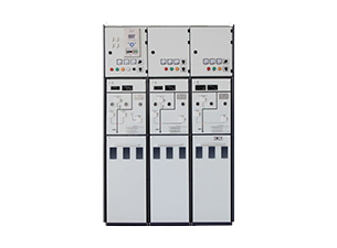
The control box and fan are important auxiliary components of the transformer:
- The core role of the control box is to manage the voltage and current through the transformer, balancing the load on the grid to ensure even and efficient distribution of power, while preventing overloads, short circuits and other faults through fuses, surge arresters, circuit breakers and other components to protect the grid and transformer safety;
- The fan, on the other hand, has multiple roles, which not only reduces the noise generated when the transformer is in operation, but also aids in heat dissipation, maintains the ideal working temperature of the equipment and enhances the stability of operation, and at the same time enhances the insulating properties, effectively dissipates static electricity, and reduces the risk of electrical accidents.
- The Pressure Relief Device (PRD) is mounted on top of the transformer tank and is used to respond to serious faults within the equipment. When a short circuit, overheating and other faults occur inside the transformer, a large amount of gas is generated.
This causes the pressure inside the tank to rise sharply, at which time the valve cover of the pressure release device will automatically open to discharge the oil and hot gases, lowering the pressure inside the tank and preventing the tank from rupturing or exploding;
When the pressure is back to normal, the valve cover will automatically close to maintain the sealing performance of the tank and avoid leakage of the insulating oil and the intrusion of impurities.
Essential Maintenance Checklist
In order to ensure the normal operation of transformer components and prolong the service life of the equipment, it is necessary to carry out regular maintenance checks. The following maintenance checklist is based on industry practice and engineering recommendations, mainly applicable to ventilated and VPI/VPE dry-type power transformers:
Visual and Mechanical Inspection
Inspect coil and core surfaces for dust, dirt, oil residue or corrosion;
- Check all bolts, clamps and busbar connections to ensure firmness without looseness and corrosion, and tighten them with wrenches if necessary to prevent vibration-induced poor contact and local overheating; clean up dust and sundries in the shells, shutters and ventilators to ensure smooth ventilation and safeguard normal cooling and dissipation of heat.
- Focus on checking the insulation of windings, iron core and wiring, check whether there is discoloration, cracking, damage or partial discharge left by scorch marks, charring and other anomalies, and find out the problem of timely shutdown to deal with, to avoid leakage of insulation failure caused by leakage, short-circuit potential hazards.
- Check the mounting bolts and vibration isolators to ensure that the bolts are not missing, no slippery wire and fastened in place, and the vibration isolators are not aging, broken and deformed, which can effectively buffer the operation vibration and reduce the loss of the internal components to ensure that the transformer is mounted stably and operated without obvious shaking.
Electrical Testing
Insulation resistance (IR) test, detecting the insulation performance between phase and phase, phase and ground, and comparing with the benchmark value provided by the manufacturer;
- Turns Ratio (TTR) test: the core is used to confirm the completeness and accuracy of the winding turns ratio, detect inter-turn short-circuit, missing turns and other hidden dangers, need to use a professional tester to connect the primary and secondary winding terminals, compare the test data with the standard value of the nameplate, and need to be shut down for maintenance when the deviation exceeds the limit.
- Winding Resistance Test: To check the potential problems of poor winding connection and local overheating, use DC resistance tester to measure the resistance of each phase winding, compare the balance of each phase and the manufacturer’s standard value, when abnormal, we need to check the junction and coil, and deal with the potential problems in time.
- Thermal Imaging Scanning: Scan the windings, terminals and other key parts with infrared thermal imager to identify hot spots caused by loose connections, overloads, etc., and stop the machine immediately to investigate and deal with any abnormalities, so as to avoid burning and short-circuiting of the windings.
- Grounding continuity check: Measure the grounding resistance with a grounding resistance tester to ensure compliance with national standards and equipment requirements, and at the same time, check the grounding leads and grounding electrodes to confirm that there is no looseness, corrosion, or breakage, to ensure that static electricity and fault currents are smoothly channeled to the earth.
Cooling and Ventilation
Normal operation of the cooling and ventilation system is the key to the stability of the transformer, need to be regularly on the relevant parts of a comprehensive inspection and cleaning. Focus on checking and thoroughly cleaning the cooling air duct:
- Focus on checking and thoroughly clean up the cooling duct, air channel and air cooling unit special fan, clean up process need to use compressed air or soft brush, one by one to remove the duct, air channel gap in the dust, flocculent, oil and other debris, to ensure that the channel is not any blockage, to avoid blockage of air ducts lead to heat dissipation is blocked;
- At the same time to strictly ensure that the transformer around the reserve enough ventilation space, in accordance with the equipment installation specifications, no accumulation around, obstacles, to ensure that the air can circulate smoothly, to provide good conditions for heat dissipation.
- In addition, need to check the fan running status, start to observe its rotation smoothness, there is no abnormal noise and speed is normal; if equipped with auxiliary cooling system, need to test the thermostatic control function, confirm the thermostatic controller can be based on the operating temperature automatically start and stop the fan, safeguard the cooling effect.
- For the closed or cabinet mounted transformer, it is necessary to focus on checking the internal filter, regularly dismantle and clean up the dust and impurities on the surface and inside of the filter, confirm that the filter is not blocked or broken, ensure that its filtration function is normal, and prevent the dust from entering the internal equipment to affect the performance of the components.
Load and Temperature Monitoring
- Regularly record the operating temperature and load current of transformer under normal operating condition, standardize the monitoring process to ensure that the collected data are accurate, complete and traceable, and provide a reliable basis for subsequent operation and maintenance analysis;
- The data obtained from monitoring, and equipment nameplate labeled temperature rise limit value, insulation level standards for accurate comparison and analysis, detailed investigation of all kinds of abnormalities in the operation of the transformer hidden danger, early discovery, early identification;
- If the transformer is found to have continuous overload, operating temperature exceeding the design rated value and other abnormalities, it is necessary to immediately carry out an in-depth investigation, accurately locate the root cause of the abnormality, and formulate scientific and reasonable targeted measures to promptly eliminate the hidden danger and restore normal operation of the equipment;
- For the key important transformer equipment, it is recommended to install temperature sensors or thermal relays to realize real-time and continuous monitoring of equipment operating temperature, to further enhance the timeliness, accuracy and effectiveness of operation and maintenance control, and to ensure the long-term stable operation of equipment.
Environmental and Safety Checks
- Evaluate the transformer operating environment, focus on monitoring humidity, dust and chemical exposure, combined with the installation scenario check: manufacturing workshop focus on preventing metal dust, oil vapor and other erosion; outdoor scenarios focus on humidity, rain, snow, wind and sand impact, to avoid the accumulation of moisture and dust damage to components.
- Check the integrity of the tank shell, carefully check whether there is damage, deformation and other anomalies, while verifying that the gasket is not aging, no cracking, to ensure that the sealing performance is good, and effectively block moisture, dust and other impurities invade the internal equipment;
- Check the status of the shell paint, if the paint is found to be damaged, it is necessary to make up for the anticorrosion coating in time to enhance the corrosion resistance of the shell to extend its service life.
- Check the grounding device and all kinds of connection parts, focusing on checking the grounding leads, terminals whether there is corrosion, loose, broken and other problems, to ensure that all connections are firm and reliable, good contact, from the source to avoid poor grounding caused by potential safety hazards, to protect the safety of equipment operation and maintenance.
- Confirm that all kinds of equipment markings, nameplates and safety warning signs are complete, undamaged and clearly recognizable, to ensure that operators can identify the equipment parameters and safety precautions in the operation and maintenance process, effectively avoiding operational errors, and further guaranteeing the standardization and safety of the operation and maintenance work.
Conclusion
The normal operation of the transformer requires the core components and auxiliary components to work together: iron core and winding as the core, bear the magnetic coupling and voltage conversion function, is the basis of the transmission of electric energy; insulation device, cooling system and other auxiliary components, for the safe and efficient long-term operation of the equipment to provide protection, each component is indispensable.
Understand the components and their role, not only can help to understand the working principle of the transformer, but also for the operation and maintenance, troubleshooting and selection of reference; pay attention to the quality of components and maintenance, can extend the life of the equipment, to ensure the stable operation of the power system, to support the production of all walks of life and daily life with electricity.