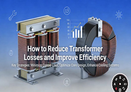
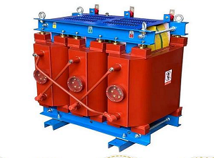
Understanding Transformer Losses
Transformer losses are the energy losses that occur during the transmission of power through a transformer. These losses are mainly categorised as no-load losses and load losses; they are a major factor in power system efficiency and also increase operating costs and carbon emissions. Controlling these losses is a critical step in improving energy efficiency and enhancing grid performance.
No-load loss
This loss exists as long as the power supply is energised, independent of the size of the load.
Mainly composed of hysteresis loss and eddy current loss
Determining factors: core material, magnetic flux density, stacking process
Load Losses
Rises sharply with increasing load current and is proportional to the square of the current (I²R).
Mainly includes winding resistance heating and magnetic leakage loss.
Determining factors: conductor material, cross-sectional area, winding structure, load factor.
Determining factors: wire material, cross-sectional area, winding structure, load factor
Design Strategies to Reduce Transformer Losses
Core Optimization: Minimize iron losses
Through the use of high permeability orientated silicon steel sheets (e.g. Hi-B and 30Q130), iron losses can be reduced by 20 to 50 per cent compared to standard silicon steel.
The use of amorphous alloy cores reduces no-load losses by 60 to 80 per cent compared to conventional silicon steel, making them ideally suited to distribution transformers that operate continuously under live conditions.
Structural optimisation: the use of full-skewed joints, trapezoidal joints and low flux density design effectively reduces the magnetic resistance and prevents local overheating.
Winding Optimization: Minimize copper losses
Reduced basic resistance by using high purity oxygen-free copper with conductivity ≥ 101% IACS
Reduction of extra losses caused by eddy currents and circulating currents by using staggered windings/combination windings.
Reasonable control of current density: 2.5-3.5A/mm² for copper wire winding to avoid overloading and heating.
Overall design upgrade
Optimisation of electromagnetic fields and reduction of stray losses through 3D simulation.
Use of efficient insulation and heat dissipation structures to enhance heat resistance and long-term stability.
Selection should be based on total life cycle cost, not just initial purchase price.
Operational Strategies to Improve Efficiency
Precisely match capacity; avoid “over-sizing”
Optimum economic load factor: 40-70 per cent for highest efficiency and lowest total losses.
Long-term load <30%: the transformer should be replaced with one of lower capacity to significantly reduce no-load losses.
If the load is continuously >85%: the capacity should be increased or operated in parallel to avoid shock losses and shortened service life due to overloading.
Optimize operating modes
Multiple transformers: Redundant units are deactivated during off-peak hours to reduce no-load losses.
Maintaining a stable operating voltage: avoiding over/under-voltage and preventing a simultaneous increase in iron and copper losses.
Improve power factor: install reactive power compensation devices to minimise additional losses due to reactive currents.
Enhance cooling and environmental management
Keep it ventilated and clean; prevent dust and oil from blocking the cooling channels.
Intelligent temperature-controlled forced air cooling: adjust the fan speed according to the demand, reduce the auxiliary power consumption by 30%-50%.
Oil-immersed transformer: regularly check the oil quality, filter the oil and replenish the oil quantity to maintain the insulation and heat dissipation performance.
Standardize Daily Operation and Maintenance
Regular inspection: Measure temperature, vibration, listen for abnormal noise, and check for oil leaks.
Timely treatment: Solve potential problems such as poor contact, three-phase imbalance and local overheating.
Avoid frequent no-load switching to reduce excitation shock losses.
Advanced Technologies for High Efficiency
New Materials and Structures
Amorphous alloy transformer: very low no-load loss, long-term operation can quickly recover the investment.
Three-dimensional laminated iron core: symmetrical three-phase magnetic circuit, can reduce the no-load current by 40%-60%.
High-temperature superconducting winding: resistance tends to zero, copper loss reduction of more than 90% (cutting-edge applications).
Intelligent Monitoring and Digital Twins
Real-time data acquisition through multiple sensors: temperature, partial discharges, gas in oil, vibrations and electrical parameters.
AI algorithm analysis: predicts insulation ageing, winding deformation and overheating risk.
Digital twin: simulation of operating conditions to support fault simulation and optimal scheduling.
Solid-state transformers
Replaces traditional core windings with power devices such as silicon carbide.
Efficiency of 98.5% or higher, 60% smaller footprint, faster response and more flexible control.
Benefits of predictive maintenance.
Core Value
Avoid unplanned downtime by providing early warning of potential failures two to four weeks in advance.
Reduces fault location time from hours to seconds, dramatically improving response efficiency.
Reduces O&M costs by 20 to 40 per cent and extends equipment life by more than 30 per cent.
Minimises additional losses due to overheating and insulation deterioration, ensuring long-term efficient equipment operation.
Implementation Approach
Deployment of online monitoring systems: including oil chromatography, partial discharge detection, fibre optic temperature measurement and vibration monitoring.
Establishment of an equipment health index model to quantitatively assess the condition of equipment (0-100 points).
Shift from ‘scheduled maintenance’ to ‘condition-based maintenance’, i.e., maintenance only when necessary.
Optimisation of operating strategies in conjunction with load forecasting to maintain efficient operation on a continuous basis.