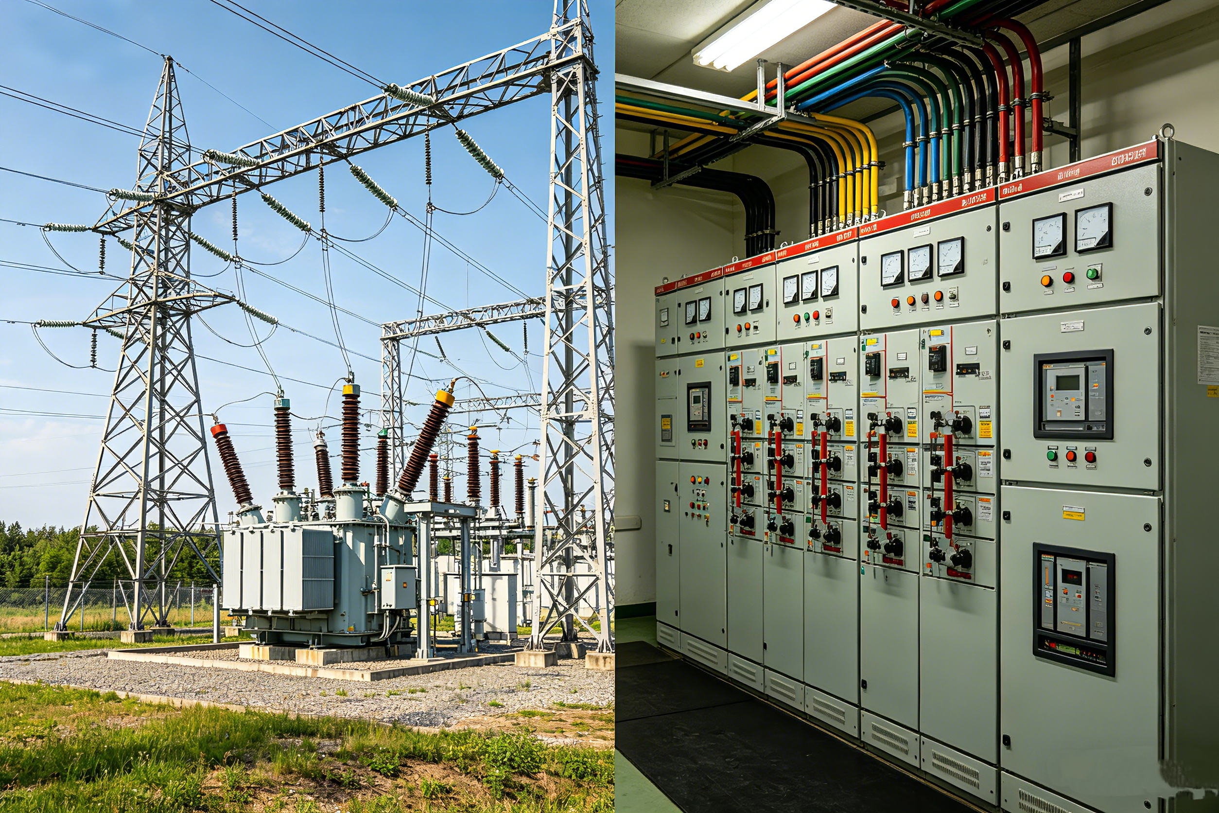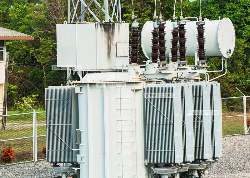


In the British substation, industrial and commercial power distribution and new energy grid-connected projects, transformer size and MVA rating are the core parameters of selection design and grid compliance acceptance.The two are very easy to confuse, which can easily cause equipment overheating, waste of energy consumption, DNO grid-connected non-compliance and other selection problems.
Relying on the official British IEC 60076, ENA specifications and local engineering experience, this article systematically analyzes the differences between transformer size and MVA rating, calculation formulas, standardized selection steps, British general rated specifications, key influencing factors and compliance requirements for selection, and provides professional guidance for the precise selection of transformers for various power projects in the UK.
Transformer Size vs. MVA Rating: What Is the Difference?
In the context of the British power industry, transformer size and MVA rating are two completely different but highly related parameters. The former focuses on the physical properties of the equipment, while the latter defines the electrical carrying capacity. The two cannot be mixed.
MVA rating (electrical capacity)
MVA (megavolt amperes) is the core unit that measures the continuous apparent power carrying capacity of transformers. It represents the maximum power load that the equipment can carry stably for a long time under rated operating conditions, without overheating, insulation aging or equipment damage. It is the core basis for transformer electrical selection.
- Unit conversion: 1 MVA = 1000 kVA = 1000000 VA; kVA is commonly used for small distribution transformers, and MVA is uniformly used for medium and large power grids and transmission transformers.
- Core characteristics: The MVA rating has nothing to do with the load power factor, which is different from the kW active power. The transformer needs to carry both active power and reactive power, so the apparent power must be used as the selection standard.
- Value basis: It is marked on the equipment nameplate and is calculated from the rated voltage and rated current of the winding. The core is subject to the thermal limit of the iron core, winding, and insulating material.
Transformer size (physical properties)
Transformer size refers specifically to the physical parameters of the equipment, including length, width and height dimensions, floor area, fuel tank capacity, overall weight (oil-immersed weight with insulating oil), iron core coil assembly volume, etc.
The physical size of the equipment is derived from the electrical capacity: the higher the MVA rating, the larger the required iron core (to avoid magnetic saturation), the thicker the conductor (to carry high current), the thicker the insulating layer (to adapt to high voltage), the more complex the cooling system, and the overall volume and weight increase.
It should be noted that the two are not strictly linear. The industry generally adopts the 0.75 proportional law: under the premise of constant magnetic flux density and current density, the volume and weight of the transformer vary with the power of 0.75 of the rated value, and the linear size varies with the fourth square root of the rated value.Therefore, transformers of the same MVA grade may have significant differences in physical dimensions due to different cooling methods, voltage levels, and structural designs.
Comparison of the core differences between the two
| Comparison Dimension | MVA Rating | Physical Dimension |
| Measurement Object | Electrical load-bearing capacity (Apparent Power) | Equipment outline, weight and installation footprint |
| Core Function | Determines the maximum bearable power load of equipment | Adapt to installation space, transportation conditions and foundation bearing capacity |
| Attribute Positioning | Core design target parameter | Derived design result (determined by iron core, winding and cooling system) |
| Influencing Factors | Voltage level, cooling mode and impedance parameter | Insulation grade, winding quantity, structure type and ambient operating condition |
| Practical Operation Notes | Fixed nameplate parameter; actual load capacity decreases under non-rated operating conditions | The selected MVA rating accurately matches equipment weight and manufacturing cost |
“Summary”: The MVA rating determines “how much electricity the transformer can carry”, and the physical size determines “how much space and how heavy the transformer is.” The selection of the British project needs to take into account the electrical capacity requirements and on-site installation conditions at the same time.

Step-by-Step: How to Calculate Transformer Size
In the actual operation of British engineering, the so-called “transformer selection size” is essentially based on the load calculation to match the corresponding standard kVA/MVA rating, and the physical size is determined by the rating, voltage level, and cooling method.The following is a standardized calculation process common to British electrical engineers, which is suitable for industrial and commercial, substation, and new energy grid-connected scenarios.
Core calculation formula
Suitable for the British 50Hz power grid system, it is divided into single-phase and three-phase formulas, and supports active power conversion at the same time.:
- Calculation of kVA of single-phase transformer: kVA = (V × I) ÷ 1000
- Three-phase transformer kVA calculation: kVA = (V × I × 1.732) ÷ 1000(√3≈1.732)
- Active power to apparent power: kVA = total kW ÷ power factor PF (when the industrial load is unknown PF, the default is 0.8)
Formula parameter description: V is the line voltage (V), I is the full load current (A), and PF is the load power factor.
Standardized selection process
Step 1: Collect full load data
Count all loads covered by transformers (motors, lighting, HVAC, industrial control equipment, data center equipment, etc.), record the voltage, current, power, phase number, and operating mode of each equipment (continuous load/intermittent load), and focus on the start-up conditions of high-power motors to avoid voltage dips caused by start-up shocks.
Step 2: Convert to kVA load
All equipment parameters are uniformly converted into kVA through the above formula; for motors marked in horsepower (HP), a special conversion formula is used: kVA ≈ (HP × 0.746) ÷ (equipment efficiency × PF), and finally the total load kVA value is summarized, which can be combined with the British BS 7671 standard to calculate the load factor and demand factor.
Step 3: Calculation based on active power correction
If the project only counts the total active power (kW), it needs to be converted into apparent power (kVA) in combination with the load power factor (PF).Taking an 80kW industrial load and a power factor of 0.8 as an example, the apparent power can be calculated as: kVA=80÷0.8=100kVA.
Step 4: Superimpose the safety margin
In accordance with the general specifications of IEEE and NEC in the United Kingdom, the continuous operating load of the transformer shall not exceed 80% of the rated value, while reserving space for future expansion.:
- Basic safety margin: uniformly reserve 1.25 times the capacity margin to offset the continuous operation limit of 80% of the rated load of the transformer to ensure the long-term stable operation of the equipment
- Expansion margin: According to the service life of the project and the later format upgrade plan, reserve 10%-25% of the capacity redundancy to adapt to the subsequent load growth needs
- Special working condition margin: For harsh working conditions such as high temperature environment, high altitude area, synchronous start-up of multiple motors, harmonic enrichment, etc., additional capacity margin is required, or the transformer is used to reduce capacity to avoid the risk of overload and heat generation.
Step 5: Match the British standard rating
After the calculation is completed, it will only be rounded up, and will never be adapted downwards. It is adapted to the British IEC R10 series standard specifications.:
Three-phase commonly used kVA:15、30、45、75、112.5、150、225、300、500、750、1000、1500、2000、2500
Single-phase commonly used kVA:5、10、15、25、37.5、50、75、100、167、250
Step 6: Parameter verification and confirmation
Check the full load current, high and low voltage voltage level, impedance value, temperature value, K coefficient (for harmonic load), and cooling method of the selected rated value. Large-scale equipment needs to convert kVA to MVA (÷1000) to match the power grid access standard.
Transformer MVA Rating Calculation Formula
MVA is a general unit for medium and high voltage power grids, substations, and transmission projects in the United Kingdom. It is suitable for large transformers above 1000kVA. The core formula is consistent with the calculation logic of kVA, but the unit conversion is different.
Basic calculation formula
- Three-phase transformer MVA: MVA = (1.732 × line voltage kV × current A) ÷ 1000
- Single-phase transformer MVA: MVA = (line voltage kV × current A) ÷ 1000
- Quick conversion: MVA = kVA ÷ 1000
Description of core features
The MVA rating of the high and low voltage side of the transformer is consistent (ignoring equipment loss), and the rated capacity can be cross-calculated through the parameters of the primary and secondary sides.The rated value of the equipment nameplate is a parameter under standard operating conditions. Under non-rated taps, insufficient cooling, and high temperature environments, the actual output capacity will be lower than the nameplate value.
Dual-rated transformers (such as 18/24MVA and 45/50MVA) are commonly used in the UK, corresponding to ONAN self-cooling and ONAF air-cooled conditions, respectively, and the capacity can be significantly increased in the forced cooling mode.
Typical Transformer MVA Ratings in the UK
The rating of British transformers strictly follows the IEC 60076 standard and ENA TS 35-1/35-6 industry specifications, and adopts the R10 preferred series (about 25% gradient). The standard specifications of different power grid levels and application scenarios are highly unified, and they are adapted to the access requirements of DNO power distribution operators and the national grid.
Low voltage distribution transformer (11kV/415V)
Suitable for power distribution in residential areas, industrial and commercial terminals, the specifications are mainly kVA, and the equivalent MVA range is 0.1-2.5MVA.:100、160、200、250、315、400、500、630、800、1000、1250、1600、2000、 2500kVA.
Primary substation transformer (33/11kV)
It is the core equipment of the British distribution network. The rated value is distinguished according to the regional load density, and the standard specifications are commonly used.:5、7.5、10、12.5、15、20、24、 30MVA.
| Region Type | Common MVA Ratings |
| High-density Urban Area | 24-30MVA |
| General Urban Area | 15-24MVA |
| Suburban Area | 7.5-15MVA |
| Rural Area | 2.5-10MVA |
Power grid trunk transformer
This type of transformer mainly undertakes the tasks of regional trunk power transmission and power distribution. The conventional capacity specification is 30–90MVA, and the mainstream selection range of the project is 40–60MVA; among them, 132kV substations in high–density urban areas are mostly selected with 30-40MVA specifications to meet regional load requirements.
High voltage transmission transformer
- 275kV voltage level: maximum 240MVA
- 400kV ultra-high voltage level: maximum 1100MVA (dedicated for national interconnected power grids and super substations)
- New energy grid-connected, unit step-up transformer: 100-500MVA mainly
Key Factors That Affect Transformer Size Selection
Accurate selection cannot only rely on load calculation. It needs to be combined with the UK’s local working conditions, power grid rules, and environmental conditions to avoid problems such as insufficient capacity, failure of compliance, and high operating losses.
Load characteristics
- Power factor: Low power factor loads will significantly increase the apparent power required by the system. If the active power is selected, it can easily cause insufficient transformer capacity, so the rated capacity of the transformer needs to be appropriately enlarged for adaptation.
- Load type: Motor loads have 5-8 times the starting inrush current, and additional capacity needs to be reserved; non-linear loads such as frequency converters, UPS, and data centers will produce harmonics, and special transformers with K coefficients need to be selected.
- Operating mode: For loads that continue to operate at full load for a long time, the operating limit of 80% of the rated load of the transformer must be strictly observed; for short-term intermittent loads, capacity redundancy can be appropriately reduced in combination with actual operating conditions to avoid waste of equipment capacity.
Power grid and voltage configuration
The British power grid adopts a unified 50Hz power frequency standard, the voltage level is clearly divided and the level is standardized. The high and low voltage matching scheme directly determines the insulation configuration, structure and capacity adaptation standards of the transformer.At the same time, the transformer winding wiring group and impedance parameters need to strictly match the fault capacity of the power grid and the voltage regulation requirements of the system to ensure the stable operation of the power grid.
Security redundancy and expansion requirements
Conventional engineering projects need to reserve 15%-30% of capacity redundancy to meet the later load growth and format upgrade needs.The British DNO public substations generally adopt an N-1 safety redundancy design, which guarantees the reliability of power supply through parallel operation of dual transformers. A single transformer needs to independently carry the core load of the whole station, so the selection capacity needs to be further rationally enlarged.
On-site environmental conditions
- Ambient temperature: The standard rated capacity of the transformer is based on the reference operating conditions of an average annual temperature of 30℃ and a maximum of 40℃. Every time the operating ambient temperature exceeds the reference value by 1℃, the equipment needs to be reduced by 1% to avoid the risk of high temperature overload.
- Installation environment: special installation scenarios with humidity, dust pollution, airtight and no ventilation need to match the exclusive cooling method and high-level protection design to ensure the stable operation of the equipment.
- Altitude: In high-altitude areas above 1000m above sea level, the efficiency of air convection and heat dissipation is greatly attenuated. For every 100m increase in altitude, the rated capacity of the equipment needs to be reduced by 0.3%.
Compliance and cost constraints
Transformer selection must strictly comply with the British EcoDesign energy efficiency standards and ENA industry specifications, take into account equipment procurement costs, long-term operating losses and equipment service life, and eliminate the problems of high no-load losses and waste of resources caused by blind large-capacity selection, so as to achieve a balance between compliance and economy.
UK Voltage Levels and Transformer Selection
The British power system adopts a hierarchical voltage transmission architecture, from ultra-high voltage cross-provincial transmission to low-voltage terminal power distribution, the voltage parameters at all levels are standardized and fixed, corresponding to the exclusive transformer specifications, structural design and technical requirements, which are the core basic basis for transformer selection in power projects.
UK grid voltage level
| Grid Level | Standard Voltage | Core Function |
| Extra-High Voltage Transmission Layer | 400kV, 275kV | Undertakes long-distance and large-capacity power transmission across regions and supports national grid interconnection. |
| Regional Transmission Layer | 132kV | Manages regional power distribution and main grid power supply, acting as a bridge between transmission and distribution systems. |
| Primary Distribution Layer | 33kV (partial 66kV) | Supplies power to regional central substations and implements secondary power distribution within the service area. |
| Secondary Distribution Layer | 11kV (partial 6.6kV) | Provides refined local power supply for residential blocks and industrial parks. |
| Low-Voltage Terminal Layer | 3-phase 400V, 1-phase 230V | Directly supplies power to commercial, industrial and residential end-user equipment to guarantee terminal power supply. |
Key points for transformer selection at all levels
- 400/275kV transmission transformer: Mostly adopts auto-coupling transformer structure, with a capacity covering 240–1100MVA, standard with on-load voltage regulating switch (OLTC) and forced cooling system, relying on high impedance design to effectively limit the short-circuit current of the system, and adapt to ultra-high voltage transmission scenarios.
- 33/11kV power distribution main transformer: It is the most widely used core transformer equipment in the British distribution network. It is commonly used in urban sites with 20–30MVA specifications, and rural sites are adapted to 5–15MVA specifications. OLTC automatic voltage regulating device is standard to ensure stable supply voltage.
- 132/33kV trunk transformer: the capacity range is 30–90MVA, with dual rated cooling conditions, supports parallel operation of multiple equipment, and can meet the requirements of N-1 high-reliability power supply of the power grid.
- 11kV/400V terminal transformer: widely used in industrial, commercial and civil construction projects, with a capacity covering 100–2500kVA, divided into two types: oil-immersed and dry-type, suitable for different installation scenarios and fire rating requirements.
UK Standards and Regulations to Check
All transformer equipment for grid-connected operation and commercial operation in the UK must strictly comply with local standards and industry regulations. Equipment compliance is a hard prerequisite for project acceptance and grid-connected power grids, which directly determines whether the equipment can be legally put into operation.
Core technical standards
BS EN/IEC 60076 series standards: It is the core technical benchmark for the design, production, testing and commissioning of transformers in the United Kingdom. It comprehensively regulates key indicators such as general technical requirements of equipment, temperature rise limits, insulation levels, short-circuit tolerance, loading standards and noise limits, covering the technical requirements of the whole life cycle of equipment.
Energy efficiency compliance standards
After Brexit, the United Kingdom will continue to follow the EU 548/2014 energy efficiency regulations, enforce Tier 2 high-level energy efficiency standards, and strictly limit transformer no-load loss and load loss parameters.All transformers with rated capacity ≥1kVA are required to meet the standards, and the PEI energy efficiency index test report is provided as the basis for compliance.
DNO grid-connected special specification
- ENA TS 35-1: Suitable for 11kV/33kV distribution network, standardize the technical parameters and grid–connected requirements of 16kVA-5000kVA small and medium-sized distribution transformers
- ENA TS 35-6: For the 33kV/132kV voltage level, clarify the design, operation and maintenance and grid-connected technical guidelines for the main transformers of medium and large power grids
Power grid access and safety regulations
- ESQCR 2002: Statutory power supply standard, regulating power supply voltage quality, power supply reliability and continuous power supply requirements
- G99 grid-connected specification: Clarify the technical conditions and safety requirements for grid-connected transformers for new energy power plants and self-owned distributed power supplies
- PCB control regulations: completely prohibit the commissioning of old transformers containing polychlorinated biphenyls, and standardize the process of scrap, disposal and renewal of old equipment
- The Power Operation Regulations of 1989 and the Occupational Health and Safety Act of 1974: regulate the safety operation specifications of the whole process of on-site installation, commissioning and operation and maintenance of transformers
How Much Transformer Capacity Do You Really Need?
The core principles of precise transformer selection are: taking into account the current actual load, long-term expansion requirements and equipment operating efficiency, to achieve accurate adaptation of capacity, and to avoid the two core problems of frequent overload failures caused by too small selection, excessive no-load loss caused by too large selection, and waste of resources.
Accurate accounting of load
The selection accounting needs to abandon the misunderstanding of simply accumulating the rated power of the equipment nameplate, and combine the simultaneous operating coefficients and demand coefficients of various types of equipment to accurately calculate the maximum comprehensive demand load of the system, based on the actual operating conditions of the equipment as the core basis, rather than the theoretical rated operating conditions.
Scientific superposition of multiple margins
Based on the calculated maximum comprehensive load, the multiple capacity margins are scientifically superimposed, including the 80% continuous load operating limit of the transformer, the 15%-25% long-term expansion margin, and the special margins for special working conditions such as harmonics, high temperature, and motor start-up impact. The comprehensive magnification is controlled in the range of 1.15-1.3 to avoid excessive selection caused by the superposition of multiple margins.
Optimal operating interval control
The optimal operating load rate of the transformer is 60%-80%, and the equipment loss in this range is the lowest, the operating stability is the strongest, and the service life is the longest.The selection of the project needs to strictly control the load interval, the peak load shall not exceed 80% of the rated capacity, and the daily operating load shall not be less than 60%. It is the standardized optimal allocation criterion for British power projects.
Avoidance of common selection misunderstandings
- Selection based on active power alone: relying solely on the active power (kW) of the equipment to calculate the capacity, ignoring the influence of the power factor on the power of the transformer, it can easily cause insufficient selection of the rated capacity of the transformer, frequent overload of equipment operation, causing problems such as heat generation, failure and shutdown.
- *Blindly superimposing safety margins: Multiple safety redundancy is superimposed without specifications and uncontrollably, resulting in excessive transformer capacity selection, long-term light-load operation of equipment, and high no-load losses, which greatly reduces the long-term operation and maintenance economy of the project.
- Ignore the factors of capacitance reduction in working conditions: adverse working conditions such as harmonic interference, high temperature environment, and heat dissipation attenuation at high altitudes are not considered in the selection of the model, and the capacitance reduction correction is not made, so that the actual output of the equipment is lower than the nameplate rating, and it is easy to continue to heat up and overload during operation.
- No long-term expansion margin is reserved: it only matches the selection of the current load requirements of the project, and does not combine the site format upgrade and load growth planning to reserve redundancy. Equipment needs to be replaced after the later load increase, which greatly increases the cost of transformation and rework.
Conclusion
The selection of the MVA capacity of the British transformer needs to be comprehensively determined in combination with load conditions, power grid conditions, expansion requirements and local specifications.Precise selection can avoid the risk of equipment overload, reduce operating losses, and ensure the safety of power supply and grid-connected compliance of various power projects.
The selection of transformers directly affects the operational safety, grid-connected compliance and economic benefits of British power projects.Relying on project working conditions and local grid-connected standards, Jinmatransformer provides accurate transformer selection solutions, taking into account equipment performance, reliability and cost advantages, and provides reliable support for various British power projects.