

The “Dual Carbon” strategy is driving the continued large-scale development of onshore and offshore wind power. As the core primary equipment for power conversion and grid-connected transmission in wind farms, transformers directly determine the power generation efficiency of wind farms, their compatibility with the power grid, and long-term O&M costs. Conventional general-purpose distribution transformers cannot adapt to the special operating conditions of wind power, such as the intermittent load of wind turbines, harmonics from power converters, coastal salt fog, and nacelle vibrations. In the early days, many wind farms that selected standard distribution transformers experienced engineering issues such as accelerated insulation aging, frequent circuit breaker trips, and long-term downtime resulting in financial losses. Based on IEC 60076, IEEE C57, and global wind power grid connection standards, this article systematically explains the system positioning of specialized wind power transformers, their two-stage step-up architecture, standardized selection criteria, cooling and insulation solutions, differentiated designs for onshore and offshore applications, installation and O&M systems, and life-cycle cost (LCC) calculation methods.
The Role of Transformers in Wind Power Systems and Their Core Grid-Connection Functions
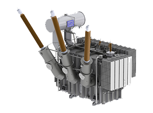
Transformers specifically designed for wind power are divided into four major categories: nacelle step-up transformers, tower-base switchgear transformers, main transformers at wind farm collection stations, and offshore DC converter transformers. Connected in series between wind turbine generators and the public transmission grid, they perform functions such as stepping up low-voltage power, reducing line losses, limiting fault currents, and improving power quality. Compared to standard distribution equipment, wind power transformers feature customized structural upgrades to address thermal cycling caused by fluctuating wind speeds, harmonic heating from power converters, high salt fog in coastal areas, and continuous nacelle vibrations. They meet the mandatory requirements for low-voltage ride-through during grid connection, eliminating the need to disconnect from the grid during power grid faults. This effectively reduces overall curtailment losses at wind farms and increases annual power generation utilization hours.
| Boosting Level | Installation Location | Input Voltage | Output Voltage | Core Function | Typical Application Scenario |
| Primary GSU Boosting | Wind Turbine Nacelle/Tower Base | 575~690V Low Voltage | 10~66kV Medium Voltage | Energy collection for single wind turbine, shortening low-voltage cables and reducing line heating loss | Onshore wind turbines, small offshore wind farms |
| Secondary Substation Boosting | Wind Farm Central Substation | 33/66kV Medium Voltage | 66~400kV High Voltage | Whole wind farm power collection, supporting long-distance high-voltage transmission | Large-scale onshore wind farms, offshore wind farms |
Operational Stresses Unique to Wind Turbine Equipment
Wind turbine equipment is subject to multiple unique operational stresses during operation: frequent starts and stops in response to wind speed fluctuations, as well as repeated load switching, cause continuous thermal expansion and contraction of insulation materials; harmonics generated by the power converter result in additional winding losses; equipment must continue to operate under load during grid short circuits and voltage sags; in coastal and offshore areas, the air has high salt content, the nacelle is subject to long-term mechanical vibration, and switch operations can cause transient overvoltages. All of these operating conditions impose higher standards on transformer insulation, heat dissipation, and corrosion resistance.
Mainstream Wind Power Transformer Categories
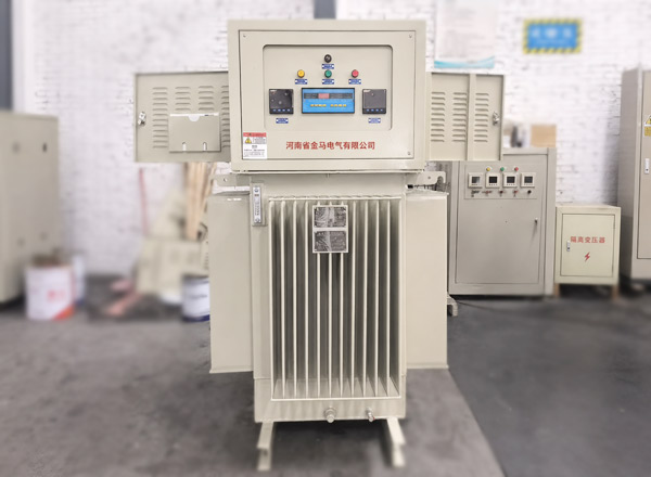
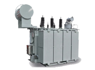
The mainstream wind power transformers on the market are divided into four categories: tower-base ground-mounted oil-immersed transformers and natural ester box-type transformers, suitable for 1 to 15 MW onshore wind turbines, with individual capacities ranging from 2 to 20 MVA; Compact dry-type transformers installed in nacelles, which pose no risk of fuel leakage, are primarily used on offshore platforms; high-capacity main transformers at collection stations handle the step-up of electrical power for the entire wind farm; and specialized DC converter transformers are used in long-distance offshore projects to support subsea cable transmission. The general parameters for a single wind turbine’s step-up transformer are 690 V on the low-voltage side and 33 kV or 34.5 kV on the medium-voltage side, with short-circuit impedance controlled within the 5% to 8% range and a 5% margin for long-term overvoltage operation.
Complete Design of the Wind Turbine Power Generation Process and Step-Up System
The wind turbine blades capture wind energy and convert it into low-speed mechanical kinetic energy. After being accelerated by a gearbox or direct-drive system, this energy drives the generator, which outputs three-phase low-voltage alternating current ranging from 575 to 690 V. The converter performs AC-to-DC conversion and adjusts the output voltage and frequency to meet grid standards, and the electrical energy is transmitted to the step-up equipment at the base of the tower or in the nacelle to complete the first stage of voltage step-up. Medium-voltage electrical energy from multiple wind turbines is transmitted via cables in a radial or loop configuration to the on-site central substation, where it undergoes a secondary step-up by the main transformer before being fed into the external transmission grid. For long-distance offshore wind projects, DC conversion equipment is added to reduce transmission losses in subsea cables.
Mandatory Constraints for Wind Power Grid Connection
Globally, wind power grid connection is subject to uniform mandatory constraints: equipment must operate stably over the long term within a voltage range of 90% to 110% of the rated voltage and a frequency range of 47.5 to 52 Hz; The system must maintain grid connection during transient voltage sags and actively supply reactive power to assist in system restoration; the power factor of the equipment must be adjustable within ±0.95, and power quality issues such as harmonics, voltage flicker, and three-phase imbalance must be strictly controlled; the system must be equipped with anti-islanding protection and precise coordinated fault trip logic, while also supporting grid ancillary services such as primary frequency regulation and inertia simulation.
Transmission Loss Control Logic
Line losses follow the law of proportionality to the square of resistive losses; increasing the operating voltage can significantly reduce current, thereby lowering heat losses caused by long-distance transmission. Losses in a single wind turbine’s step-up transformer are controlled within 1%, while losses in the main transformer at the collection station range from approximately 0.5% to 1%, and losses in high-voltage transmission lines range from 2% to 4%. During the project design phase, energy losses over the entire lifecycle can be continuously minimized by appropriately selecting the medium-voltage collection level, configuring reactive power compensation devices, and selecting low-loss core transformers.
Comprehensive Standardized Selection System for Wind Power Transformers
There are significant differences in the types of transformers suitable for onshore open sites and offshore turbine nacelles. The advantages and disadvantages of different solutions are compared as follows:
| Equipment Type | Cooling Method | Core Advantages | Disadvantages | Application Scenario |
| Mineral Oil-Immersed Transformer | ONAN/ONAF | Excellent heat dissipation performance, lower procurement cost for large capacity | Risk of oil leakage and fire | Open space at onshore tower base |
| ANatural Ester Oil-Immersed Transformer | KNAN/KNAF | High flash point, biodegradable, stronger corrosion resistance | Higher procurement price than mineral oil models | Onshore wind turbines in coastal and ecological protection areas |
| Epoxy Dry-Type Transformer | AN/AF | No liquid medium, fireproof and maintenance-free, strong vibration resistance | Higher operating loss at the same capacity | Offshore nacelles, wind farms in suburban areas |
Key Electrical Parameters for Fan Step-Up Transformers
The key electrical parameters for selecting fan step-up transformers must be fully specified. The standard voltage ratio is 0.69 kV/33 kV or 0.69 kV/34.5 kV, with tap changer settings of ±2×2.5% to accommodate grid voltage fluctuations; The equipment’s rated capacity should be 1.1 to 1.25 times the installed power of the wind turbines, with a 10% to 20% margin for gust-induced overloads; short-circuit impedance should be 5% to 8 to suppress fault short-circuit currents; insulation should use Class F or Class H high-temperature-resistant materials, with lightning impulse withstand voltage higher than that of standard distribution equipment, and the overall structure should be designed for high-harmonic operating conditions.
Logic Behind Differentiated Equipment Selection for Onshore and Offshore Projects
Onshore and offshore projects differ significantly in terms of environment and O&M conditions; therefore, equipment selection criteria must be established separately. Onshore projects have ample site space, and O&M vehicles can directly access the equipment area; oil-immersed solutions are preferred to control initial investment. Offshore platforms have limited space, high hoisting and O&M costs, and severe salt fog corrosion; equipment must be lightweight, highly corrosion-resistant, and low-maintenance, making dry-type or natural ester models the preferred choice. Differentiated selection allows for targeted adaptation to site conditions, significantly reducing the probability of equipment failures in the medium to long term.
Specialized Design for Cooling, Insulation, and Environmental Protection
Mainstream Wind Power Cooling Solutions
There are four mainstream cooling solutions for wind power projects: ONAN (oil-natural air cooling) features a simple structure and low maintenance requirements, making it suitable for onshore wind turbines with stable loads; ONAF (oil-forced air cooling) incorporates cooling fans to increase peak output by 20% to 50% and is widely adopted in high-wind areas; AN dry-type natural air cooling is used for equipment with compact nacelles, while AF forced air cooling is suited for high-temperature operating environments; KNAN natural ester cooling balances fire protection and heat dissipation and is commonly used in coastal wind farms. Equipment temperature rise is standardly controlled within the range of 55 to 65°C, with a margin for high-temperature operation.
Characteristics of the Two Insulation Systems
Insulation systems are divided into two main categories: oil-immersed insulation and epoxy dry-type insulation. Oil-immersed equipment uses insulating paper combined with mineral oil or natural ester liquids, offering strong self-healing capabilities and excellent thermal conductivity; dry-type equipment uses integrally cast epoxy resin, eliminating the risk of liquid leakage and providing outstanding high-temperature resistance and vibration resistance. Both insulation types enhance resistance to thermal cycling, suppress partial discharge caused by harmonics, and are designed to accommodate the variable load characteristics of fan operation.
Environmental Protection Requirements for Multiple Scenarios
For conventional inland sites, an IP54 protection rating is sufficient; for coastal and offshore areas, the ISO 12944 C5-M marine corrosion protection standard is implemented, with the entire unit featuring hot-dip galvanizing and a polyurethane anti-corrosion coating, and key components made of stainless steel. The equipment enclosure is equipped with a space heater to prevent internal condensation caused by diurnal temperature fluctuations; in seismically active areas, seismic reinforcement structures are added, and the equipment in the machine room is fitted with optimized vibration-damping bases.
Solutions for Improving the Long-Term Operational Reliability of Transformers
Hardware Structure Optimization Measures
Optimizing the design at the factory level can significantly extend the service life of the equipment. Selecting a disc-type winding structure enhances resistance to short-circuit surges and harmonic heating; pairing this with low-loss silicon steel or amorphous cores substantially reduces annual no-load losses; equipping the transformer with fiber-optic winding temperature monitoring, oil chromatography monitoring, and partial discharge sensors enables real-time detection of early-stage internal faults; The lightning impulse withstand voltage rating is increased, and surge arresters are installed to suppress transient overvoltages.
Optimization Approach for Wind Farm Systems
Comprehensive optimization of the wind farm system is equally critical. Installing static var generators (SVGs) and capacitor compensation cabinets within the substation helps balance reactive power and reduce sustained heating of the transformers; conducting power flow, short-circuit, and harmonic simulations during the project’s early stages ensures proper matching of transformer impedance and capacity, thereby preventing long-term operation of equipment beyond its design load.
Installation Standards, O&M Systems, and Online Monitoring
Key Points for Standardized Installation Control
Onshore oil-immersed transformers must be installed on a level concrete foundation, equipped with an oil containment basin and drainage structure, and fitted with vibration-damping pads to reduce vibration transmission; for dry-type equipment in nacelles, the total unit weight must be strictly controlled, and vibration-damping connections must be made with the wind turbine structure; offshore equipment employs a modular design to simplify the offshore hoisting process. Equipment wiring must incorporate stress relief measures, and enclosures must be sealed to prevent moisture intrusion. Prior to commissioning, a full suite of factory and on-site tests—including insulation resistance, turns ratio, and protection interlocking—must be thoroughly conducted.
Operations and maintenance (O&M) for wind power projects are divided into two mainstream models, with distinct differences in applicable scenarios and overall costs:
| Operation and Maintenance Mode | Implementation Method | Application Scenario | Comprehensive Cost |
| Regular Preventive Maintenance | Fixed-cycle on-site inspection, annual oil sample testing | Small and medium-sized onshore wind farms | Medium, high investment in manual inspection |
| Predictive Condition-based Maintenance | On-demand maintenance based on online monitoring data | Offshore, large-scale wind farms | Monitoring equipment installed in the early stage, lower long-term operation and maintenance costs |
Core Monitoring Indicators for Online Monitoring
Given the high costs associated with ship and helicopter access for maintenance at offshore projects, priority is given to establishing a comprehensive online monitoring platform. Key indicators for routine monitoring include winding and top-level oil temperatures, dissolved gas composition in oil, moisture content, partial discharge signals, equipment vibration, real-time load, and harmonic data. All data is integrated into the wind farm’s central SCADA system, where early warning functions enable proactive fault prediction, thereby reducing the number of unplanned outages.
Energy Efficiency, Service Life, and Total Life Cycle Cost Assessment
The design service life of wind power transformers must align with the 25- to 30-year operational cycle of the entire wind turbine. Total life cycle costs encompass all expenses, including equipment procurement and transportation, on-site installation, decades of power losses, periodic maintenance, power generation losses due to failure-related downtime, and end-of-life disposal costs; therefore, the cost-effectiveness of equipment cannot be judged solely based on the initial quotation. Adopting low-loss, wind-power-specific models involves a slight increase in upfront procurement costs; however, the long-term savings in electricity costs and reduced downtime losses can quickly offset this premium, and this advantage is even more pronounced in offshore projects.
Breakdown of Total Life Cycle Cost
Total life cycle cost is primarily divided into five components: equipment procurement, transportation, and installation costs; no-load and load power losses generated during 25 to 30 years of operation; annual maintenance, spare parts, and online monitoring and operation expenses; lost power generation revenue due to outages caused by equipment failures; and environmental disposal costs upon equipment decommissioning.
Economic Considerations for Wind Farm Site Selection
Economic assessments for wind farm site selection must take site conditions into account. High-quality wind farms with high wind speeds and high electricity prices should prioritize high-efficiency, low-loss models; for offshore projects, equipment reliability and maintenance-free performance should be the primary selection criteria; For small-scale, grid-parity onshore wind farms, the initial equipment procurement cost should be balanced while meeting specific wind power standards.
Summary of Industry Development Trends
The wind power transformer industry is currently evolving toward environmental sustainability, digitalization, and lightweight design. SF6-free insulation, end-to-end online monitoring, and compact offshore equipment have become mainstream R&D directions. Grid connection regulations in various countries are becoming increasingly stringent, imposing higher requirements on equipment in terms of harmonic control, voltage ride-through, and energy efficiency metrics. By following standardized selection criteria during the project’s early stages—and comprehensively evaluating equipment based on site conditions, load characteristics, and full-lifecycle economic benefits—wind farms can ensure long-term, stable grid connection while continuously reducing O&M and energy loss costs.