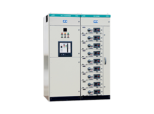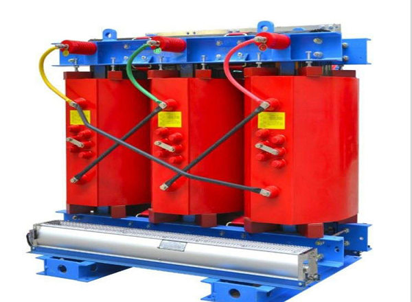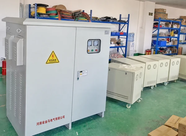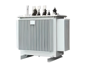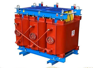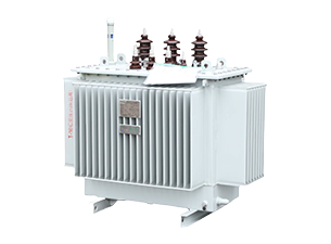


In the modern AC power system, transformer is an indispensable core power equipment, which undertakes the key functions of power conversion, voltage regulation, power transmission and distribution. Whether it is large-scale thermal, hydraulic and nuclear power stations, photovoltaic and wind power stations, or urban power grids, industrial parks, commercial buildings and residential power distribution systems, they are inseparable from the support of transformers.
Among the many transformer categories, step-up transformers and step-down transformers are the two basic types that are most widely used and have the largest market demand. The two work based on the same electromagnetic induction principle, but there are significant differences in structural design, winding configuration, electrical parameters, and operating characteristics, and they are adapted to completely different power conditions.
What Is a Step Up Transformer?
Definition and Working Principle of Step Up Transformer
The step-up transformer is a static power device used to raise the AC voltage. The core feature is that the number of turns of the secondary winding is more than that of the primary winding (Ns>Np). Its electrical characteristics are boosting and reducing current, which can realize long-distance transmission of electric energy under the premise of greatly reducing line loss. It is the core equipment of high-voltage transmission and power station grid connection.
The step-up transformer works based on Faraday electromagnetic mutual inductance principle, with no moving parts, high stability and low maintenance. The working process is as follows: alternating current is applied to the primary to generate an alternating magnetic field, the laminated iron core forms a changing magnetic flux and couples the secondary winding, and a higher electromotive force is induced by more turns of the secondary, thus completing the boost conversion. The ideal transformer core formula: voltage ratio Vs/Vp = Ns/Np, current ratio Is/Ip = Np/Ns, the overall power of the equipment is basically conserved. Boost transformer generally adopts iron core type or shell type structure, laminated iron core effectively reduces hysteresis and eddy current loss, winding regular arrangement and multi-layer insulation treatment, high magnetic coupling efficiency, stable operation, can be long-term adaptation to high-power transmission scenarios.
Key Features of Step Up Transformer
The core decision of the step-up transformer is based on the turns ratio Ns/Np>1, and the step-up and step-down current characteristics are stably realized. The power of the equipment is basically conserved, the overall loss is only 3%-5%, the utilization rate of electric energy is high, and the transmission efficiency and operation economy are taken into account.
The winding structure is highly targeted: the primary is the low-voltage high-current end, and the thick wire is used to ensure the current carrying capacity and avoid overheating; the secondary is the high-voltage small-current end, and the thin wire is used with high-strength insulation to improve the withstand voltage and high-voltage operation safety. The device only supports alternating current conversion, the operating frequency is exactly the same as the input, and it is adapted to the power frequency standard of the power grid. The efficiency of power grade step-up transformer can reach 95%-99%, and the loss is mainly copper loss, iron loss and a small amount of stray loss. As a static equipment, it has no wear, low noise, low failure rate and long life. The design focuses on strengthening the secondary high-voltage insulation, which can effectively avoid high-voltage breakdown faults and ensure the safe and stable operation of the transmission system.
What Is a Step Down Transformer?
Definition and Working Principle of Step Down Transformer
Step-down transformer is the core equipment of power grid distribution, which is mainly used to convert high-voltage transmission voltage into terminal available low-voltage electricity. Its structure is opposite to the step-up transformer, the number of secondary winding turns is less than the primary (Ns<Np), the core electrical characteristics are step-down, increase current, widely used in all kinds of terminal power distribution scenarios.
The step-down transformer and the step-up transformer are of the same origin, and both work based on the principle of Faraday electromagnetic induction mutual inductance. The primary winding on the high-voltage input side is energized to generate an alternating magnetic flux, which couples the induced electromotive force of the secondary winding. Due to fewer secondary turns, the output voltage is reduced and the current is increased, which is stably adapted to the all-weather continuous power distribution conditions of the power grid. The electrical conversion formula is completely consistent with the step-up transformer, and follows the law of inverse ratio matching of turns, voltage and current and power conservation. Under typical working conditions, when the number of primary turns is 10 times that of the secondary, the output voltage is reduced to 1/10 and the current is increased by 10 times. The equipment adopts laminated iron core to reduce eddy current loss, the primary high-voltage side adopts thin wire + high-strength insulation and withstand voltage, and the secondary low-voltage side adopts thick wire to enhance the current-carrying capacity, and the structural design is highly targeted.
Key Features of Step Down Transformer
The core determination standard of step-down transformer is turns ratio Ns/Np<1, which relies on step-down and current-increasing characteristics to realize safe power distribution. It is the mainstream equipment of civil, industrial and commercial power system, and its application coverage is much larger than that of step-up transformer.
The operating power of the equipment is basically conserved, and the loss level is similar to that of the step-up transformer. The high-voltage side has many turns, fine wire diameter and high insulation grade, which can withstand the high-voltage impact of the power grid. The low-voltage side has few turns, thick wire diameter and strong current-carrying capacity, which can stably match the high-current load demand of the terminal and take into account the safety of electricity and the stability of power supply. The equipment only supports AC power conversion, input and output frequency is constant, and it is suitable for domestic 50Hz power frequency power grid. The efficiency of distribution grade step-down transformer can reach 95%-99%, and the loss is mainly copper loss and iron loss. In view of the secondary high current heating problem, the equipment optimizes the winding heat dissipation structure to effectively avoid overload high temperature fault. The step-down transformer is designed for static and no moving parts, with low noise, no wear, low failure rate, long life and easy operation and maintenance. The equipment design focuses on strengthening the insulation protection of the primary high-voltage side, adapting to the high-voltage input conditions of the power grid, and ensuring the long-term safe and stable operation of the distribution system.
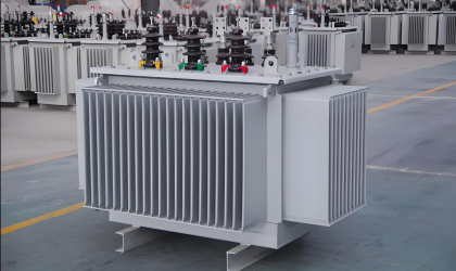
Step Up Transformer vs Step Down Transformer: Key Differences
Voltage Transformation Difference
At the core functional level, the two types of transformers form a fully complementary power conversion role. The core function of the step-up transformer is to raise the voltage and adapt to the long-distance transmission scenario of electric energy, and the core function of the step-down transformer is to reduce the voltage and adapt to the terminal power consumption scenario, which together constitute the power grid voltage regulation system.
The ratio of turns is the most important difference between the two. The number of secondary turns of the step-up transformer is greater than the number of primary turns, and the turns ratio is greater than 1. The number of secondary turns of the step-down transformer is less than the number of primary turns, and the turns ratio is less than 1. These 1 structural differences directly determine the electrical transformation characteristics of the two types of equipment.
The voltage operation parameters are significantly different, the output voltage of the step-up transformer is greater than the input voltage, which realizes the low voltage to high voltage, and the output voltage of the step-down transformer is less than the input voltage, which realizes the high voltage to low voltage. In the actual power grid operating conditions, the common operating conditions of the step-up transformer are 11-15kV low voltage to 132-400kV high voltage. Step-down transformer is responsible for multi-stage step-down work, the typical working condition is 400kV/220kV ultra-high voltage step by step down to 33kV, 11kV medium voltage, and finally to 400V/230V civil standard voltage. It is worth noting that during the operation of the two types of equipment, the grid frequency remains constant without any loss and offset.
Winding and Design Differences
The winding design of the two types of transformers is completely reverse layout, which is also the most intuitive structural feature to distinguish the two. The primary of the step-up transformer is a low-voltage high-current end, with fewer winding turns and thick wires, without high-strength insulation, and the focus is on ensuring the current-carrying capacity. Its secondary is a high-voltage and small-current terminal, with many winding turns and thin wires. It is matched with thickened insulation materials and focuses on improving the withstand voltage performance.
The winding design of the step-down transformer is just the opposite. The primary is the high-voltage and low-current end, the winding has many turns, the wire is thin, and the insulation level is extremely high, which can withstand long-term high-voltage operation. Its secondary is a low-voltage high-current end, with fewer winding turns and thick wires, giving priority to ensuring stable high-current output and adapting to terminal load requirements.
The emphasis of insulation design is obviously different, and the insulation protection core of the step-up transformer is concentrated on the secondary high voltage side to avoid high voltage discharge and breakdown fault. The insulation protection core of the step-down transformer is concentrated on the primary high-voltage side to resist the voltage fluctuation and impact of the high-voltage power grid at the input end.
There are some differences in the overall equipment structure specifications, step-up transformers are mostly large power equipment, the design focus on optimizing the basic impact insulation level (BIL), adapted to the harsh conditions of high-voltage transmission. Step-down transformers are mostly distribution-grade equipment with more compact structure, and the design focuses on heat dissipation management and high-current working condition stability.
Current and Efficiency Differences
The current transformation law is one of the core differences between the two types of equipment, the output current of the step-up transformer is less than the input current, and the high-voltage low-loss transmission is realized by reducing the current. When the step-down transformer is running, the output current is greater than the input current, and the high-power power demand of the terminal equipment is met by increasing the current.
At the power balance level, the two types of equipment follow exactly the same operating rules, the input power and output power are basically the same, there is only a small amount of equipment loss, and the power conservation characteristics are stable. Whether it is boost or buck conditions, there will be no significant power attenuation problem.
At the operational efficiency level, the performance of the two types of equipment is basically the same, and the efficiency of large power step-up transformers and distribution step-down transformers can be stable in the range of 95%-99%, with excellent long-term operation economy. The loss types of the two are the same, mainly winding copper loss and iron core loss, with a very low proportion of stray loss.
The impact of actual operating losses is different, and the step-up transformer greatly reduces the I²R loss of the transmission line by reducing the current, which perfectly solves the energy consumption problem of long-distance transmission. The step-down transformer has no long-distance transmission requirements, but the secondary high-current operating conditions will produce a certain winding heating loss, so the equipment has higher requirements for heat dissipation design.
Application Comparison
The application scenario of step-up transformer is highly focused on power generation and transmission, and is the core equipment for grid-connected and long-distance transmission of various power stations. It is mainly adapted to traditional power stations such as thermal power, hydropower and nuclear energy, as well as new energy scenarios such as photovoltaic power stations, wind farms and energy storage power stations, and is mostly used for generator booster stations and grid transmission first ends.
The application scenarios of step-down transformers focus on the transmission end and distribution and power consumption links, covering a wider range. Mainly used for transmission substations at all levels, urban and rural distribution areas, industrial parks, commercial complexes, residential areas, while adapting to various types of electronic equipment power adapters, low-voltage control circuits and other small scenes.
On the whole, the two types of equipment have a clear division of labor and complement each other. The step-up transformer is responsible for boosting the voltage at the source to achieve high efficiency and low loss of electric energy for long-distance transmission; the step-down transformer is responsible for terminal step-down, converting high-voltage electric energy into safe and available low-voltage electric energy, and jointly supporting the stable operation of the entire AC power system.
Applications of Step Up and Step Down Transformers in Power Systems
Renewable Energy Applications
Photovoltaic, wind power, energy storage and other new energy generation scenarios are the core application areas of step-up transformers. The power generation voltage of new energy equipment is generally low and cannot be directly connected to the high-voltage power grid. It must pass through multi-stage boost conversion to achieve grid-connected transmission. The boost transformer plays an irreplaceable role in this process.
In the power generation condition of photovoltaic power station, the output voltage of inverter is usually in the low voltage range of 400V-1.5kV, which can not meet the requirements of grid connection. The power station will increase the low-voltage power to 33kV and 34.5kV medium voltage through the power collection step-up transformer, and then further increase to 132kV-345kV high voltage through the large generator set step-up transformer and connect to the public transmission grid.
The application logic of the wind farm is basically the same as that of the photovoltaic power station. The output voltage of the fan generator is only 690V to several kV. A single fan is equipped with an independent small step-up transformer to raise the voltage to the standard voltage of the collector line. Finally, through the substation large-scale booster equipment, unified boost to the transmission voltage, to achieve centralized grid connection. Offshore wind farms will also use anti-corrosion, waterproof customized step-up transformers to adapt to the harsh conditions of the sea.
Energy storage power station and optical storage integrated power station also rely on step-up transformer to complete the grid connection, energy storage inverter output low-voltage power, through multi-level boost after access to the grid. In view of the fluctuation of new energy power generation and the characteristics of many harmonics, the new energy special step-up transformer will be equipped with K-coefficient anti-harmonic design and on-load voltage regulation device to ensure stable voltage output.
In the new energy power station, it will also be equipped with a small number of step-down transformers, which are mainly used for local loads such as power supply of auxiliary equipment of the power station, control system, on-site lighting, etc. The power specification is small, does not belong to the core equipment of the power station grid connection, and only guarantees the daily operation and maintenance power consumption in the station.
Power Transmission and Distribution Applications
The traditional power transmission and distribution system adopts the classic hierarchical mode of “power generation-boost-transmission-buck-use”, and the two types of transformers perform their respective duties to form a complete power transmission system. At the power generation end, the output voltage of thermal, hydraulic and nuclear power generating units is generally 11kV-25kV medium and low voltage, which can not meet the demand of long-distance transmission.
Therefore, the power station will be equipped with a special GSU generator step-up transformer to increase the output voltage of the unit to 132kV, 220kV, 400kV or even higher UHV levels. Through the high-voltage low-current transmission mode, the line resistance loss is minimized, and the long-distance and efficient transmission of large quantities of electric energy is realized.
After the high-voltage electric energy is transmitted to the urban and regional power grid, it needs to complete the voltage step-by-step reduction through the multi-stage step-down transformer. First of all, through the main substation step-down equipment, the ultra-high voltage is reduced to 66kV, 33kV, 11kV medium voltage, to meet the power demand of industrial plants, large buildings.
Subsequently, the medium voltage is further reduced to 400V/230V civil standard voltage through transformers and box-type transformers on the station posts of the block to adapt to the daily electricity consumption of residents and small commercial equipment. Most step-down transformers at all levels are equipped with on-load voltage regulating devices, which can automatically adjust the voltage according to the load fluctuation of the power grid to ensure the stability of power supply.
Industrial and Commercial Applications
In industrial parks, commercial complexes, hospitals, data centers, universities and other large places, step-down transformers are the core power distribution equipment and occupy an absolute dominant position. The grid access voltage in such places is mostly 11kV and 33kV medium and high voltage, which must be converted to the available voltage of the equipment through the step-down transformer.
The industrial plant reduces the medium and high voltage power to 690V, 480V, 400V and other industrial standard voltages through special distribution transformers to meet the operating requirements of large motors, production line equipment and control systems. At the same time supporting small step-down equipment, output 24V, 110V and other low voltage, for equipment control circuit, lighting system.
For factories and parks equipped with self-contained generator sets and distributed photovoltaics, small step-up transformers will be provided. The excess power generation in the plant can be connected to the public power grid after being boosted by the step-up transformer, so as to realize the surplus power grid, improve the energy utilization rate and reduce the power consumption cost.
In terms of equipment selection, dry-type transformers are preferred for indoor industrial and commercial scenarios, which have the advantages of oil-free, fire-proof, low noise, maintenance-free, and higher safety. Outdoor plant area, substation scene more oil-immersed transformers, better cooling effect, lower cost, suitable for high-power conditions.
How to Select the Right Step Up or Step Down Transformer
Confirm Voltage Requirements
The first step in transformer selection is to clarify the input and output voltage parameters, and to determine whether to use a step-up or step-down transformer according to the voltage difference between the power supply side and the load side. During design, a voltage fluctuation tolerance of ± 5% ~ ± 10% shall be reserved. For frequent load fluctuation scenarios, an on-load voltage regulating switch (OLTC) can be configured to ensure continuous stability of the output voltage.
Equipment frequency must be strictly matched with the system, the domestic standard is 50Hz, overseas mostly 60Hz, frequency mismatch will lead to equipment heating, capacity attenuation, shortened life. At the same time, it is necessary to select and adapt the winding group, such as Dyn11 and YNd1, in combination with the grounding mode of the power grid and the harmonic working condition. According to the voltage level matching corresponding BIL basic impact insulation level, effectively resist the impact of lightning, short circuit, voltage surge and other abnormal conditions.
Determine Transformer Capacity
Transformer capacity to kVA as the unit of accounting, capacity is too small easy to overload overheating, too large will increase the purchase cost and no-load loss, need to accurately calculate and reserve a reasonable margin. The standard calculation formula is as follows: single-phase transformer: kVA = V×I/1000; Three-phase transformer: kVA = V×I×√ 3/1000.
For conventional continuous load, the basic capacity shall be configured according to 125 of the actual load, and an additional margin of 15% ~ 25% shall be reserved for later expansion. The impact load of motor type needs to increase the capacity margin by 25% ~ 50%; For nonlinear loads such as frequency converter, photovoltaic inverter and UPS, K-coefficient anti-harmonic transformer shall be selected to avoid the problem of harmonic heating and damage.
The environmental conditions shall be corrected for capacity reduction, and the standard transformer shall be adapted to the environment below 40 ℃ and the altitude below 1000m. For every 100m rise in high altitude area, the capacity of self-cooling equipment needs to be reduced by 0.3. High temperature, high altitude and harsh scenes need to appropriately enlarge the capacity or choose a special model, the final capacity of the unified round for the national standard specifications.
Select Suitable Transformer Type
According to the installation scenario, safety requirements, cooling mode to choose the appropriate model, the mainstream type is divided into dry, oil-immersed, column/box 3 categories. Dry-type transformer includes vacuum dipping paint, resin casting structure, oil-free fire prevention, low noise, maintenance-free, suitable for data centers, hospitals, high-rise buildings and other indoor scenes, the disadvantage is the same capacity volume is too large, higher cost.
Oil-immersed transformers use mineral oil or ester oil for heat dissipation, with excellent heat dissipation performance, high power cost performance, and outstanding operating efficiency. They are widely used in outdoor substations, power stations, and industrial parks. The disadvantage is the existence of oil leakage and fire risk, the need for regular maintenance of oil.
Column, box-type transformer compact structure, weather resistance, waterproof and dustproof, suitable for urban and rural power distribution, photovoltaic collection lines and other low-voltage scenarios, capacity and voltage level limit is low. At the same time, the selection should be matched with single-phase/three-phase system and cooling level (ONAN/ONAF/OFAF). The conventional impedance of distribution transformer is 4% ~ 8%. The high impedance model can effectively limit short-circuit current and improve system safety.
Consider Operating Environment
The site environment directly determines the transformer structure, protection level and service life, and requires targeted selection and adaptation. Installation scene level, indoor priority dry fire prevention models, to avoid fire hazards, outdoor priority oil-immersed or high-protection box equipment, suitable for outdoor all-weather conditions.
Temperature and altitude are the core influence parameters, long-term high temperature environment will reduce the heat dissipation efficiency, need to choose high temperature model or enlarge capacity. When the altitude is more than 1000m, the air is thin and the heat dissipation is poor. The high altitude capacity reduction compensation design must be adopted to prevent the equipment from overheating and aging.
In view of the harsh environment such as coastal salt spray, chemical dust and wet corrosion, it is necessary to improve the IP and NEMA protection level, adopt sealing structure and anti-corrosion coating, and prevent insulation aging and equipment corrosion. Earthquake-prone areas need to use models that meet the IEEE 693 seismic standards. Residential areas, indoor scenes priority compact, low noise equipment, to meet the spatial layout and noise reduction requirements.
Transformer Manufacturer and Customized Solutions
Customized Transformer Design
For non-standard, harsh and special conditions, regular transformer manufacturers can provide standardized customized design services, through exclusive engineering design, testing and production processes, to match the special power needs of various subdivided scenarios, to ensure equipment adaptability and long-term operation stability.
The customization process begins with demand collection, and the manufacturer confirms the user’s key parameters: primary and secondary voltage, rated capacity, frequency, phase number, wiring group, impedance, temperature rise level, installation environment, protection level and accessory requirements.
Then it entered the engineering design stage, and the technical team completed the comprehensive calculation of magnetic field, temperature, insulation and mechanical structure through finite element simulation. Targeted optimization of iron core, winding layout, insulation system and cooling mode, to create a special structure suitable for non-standard working conditions.
After the scheme is approved, prototype trial production will be carried out as required, and mass production will be carried out after passing the test. All equipment are completed routine test and type test, through the user FAT factory acceptance after delivery, the whole process follows the industry standard.
Common customized configurations include non-standard transformer ratio, multiple secondary windings, K-factor anti-harmonic design, wide-range on-load voltage regulation, compact structure, anti-corrosion, waterproof and explosion-proof design and intelligent monitoring module, which can be fully adapted to harsh scenarios such as new energy, offshore wind power, chemical industry and mining.
Transformer Standards and Quality Control
The production of high-quality transformers must strictly follow international and domestic general standards. The core specifications include IEC 60076, IEEE C57, China GB, EU EN, etc. At the same time, it matches the energy efficiency and safety certification of various countries to ensure equipment compliance and versatility.
Professional manufacturers have a complete quality traceability system, strict quality inspection of iron cores, conductors, insulation materials and other raw materials, put an end to inferior materials into production, and control the quality of equipment from the source.
Inspection of the whole production process, strict control of winding, core stacking, equipment assembly, drying and other key links. Each finished product is required to complete a full set of routine tests such as ratio, polarity, winding resistance, loss, and insulation.
Representative models shall be subject to type tests such as temperature rise, short circuit tolerance, lightning impulse and noise to fully verify equipment performance. All drawings, test reports and material certificates are archived throughout the process to achieve quality traceability and performance standards.
Complete Transformer Solutions for Different Applications
High-quality transformer manufacturers not only provide a single device, but also cover the entire chain of power generation, transmission, distribution and power consumption, and provide one-stop customized power solutions to adapt to the differentiated working conditions of the whole industry.
For power generation and grid-connected scenarios, high-insulation, high-resistance short-circuit GSU step-up transformers are provided; for photovoltaic, wind power, energy storage new energy scenarios, anti-harmonic, weather-resistant, compact special transformers are provided to adapt to the fluctuation characteristics of new energy power generation.
For power transmission and distribution systems, large power transformers, autotransformers, phase-shifting transformers and complete sets of power distribution equipment are provided; for industrial and commercial scenarios, fire-resistant dry-type and low-noise power distribution transformers are provided to meet the needs of indoor safe power consumption and production power distribution.
For marine, mining, chemical, medical and other special scenes, can be customized anti-corrosion, explosion-proof, isolation, seismic special equipment. At the same time, it provides the whole process services of preliminary survey, scheme design, installation and commissioning, after-sales operation and maintenance, and equipment renovation, forming a complete power supporting guarantee system.
Summary
Step-up transformer and step-down transformer rely on the same principle of electromagnetic induction, relying on the difference of winding structure to achieve completely opposite electrical functions, is the core of modern AC power system equipment, the two complementary cooperation, constitute a complete power system of power generation, transmission, distribution, electricity.
The step-up transformer is mainly used for power station power generation and long-distance high-voltage transmission, which greatly reduces line loss and improves transmission efficiency by boosting and reducing current; the step-down transformer focuses on power distribution at the end of the power grid and converts high voltage into safe low voltage step by step to meet the power demand of industrial, commercial and civil equipment.
User selection should be combined with voltage parameters, load capacity, environmental conditions, use of the scene to accurately match the model, scientific accounting capacity, structure and protection configuration. For non-standard and harsh conditions, it is necessary to select manufacturers with professional customization capabilities, perfect quality control system and full-process services to ensure the long-term safe, stable and efficient operation of transformers.