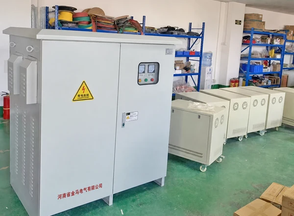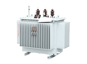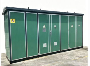


Electric transformerare the key passive equipment of the power system, which runs through the whole process of power generation, transmission, distribution, and use, and are responsible for voltage conversion and power regulation.Most users focus on its working principle, transmission function, selection method and operation and maintenance points.
This article will disassemble the core knowledge of electric transformerin an all-round way from the nine dimensions of basic definition, core working principles, structural composition, classification, energy efficiency advantages, loss causes, application scenarios, selection methods, and fault maintenance to help you thoroughly understand the operating logic and practical value of transformers.
What Is an Electric Transformer?
Electric transformerare passive electrical equipment. The core relies on the principle of electromagnetic induction. Under the condition that the circuit is not directly electrically connected, the cross-circuit transmission of electrical energy can be completed, and key power control functions such as voltage rise and fall, electrical isolation, and impedance matching can be realized. It is the basic core equipment of the power system.
The transformer only transmits electrical energy through electromagnetic coupling, does not involve the conversion of mechanical energy and electrical energy, and the operating loss is extremely low.Its core feature is that it is only suitable for alternating current (AC) operation and cannot directly convert direct current (DC) voltage. This is also the basic principle boundary of transformer operation.
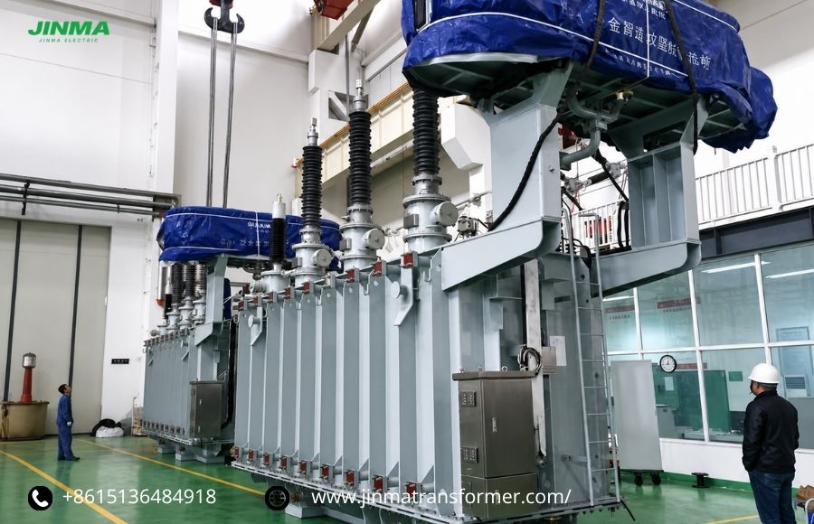 https://www.jinmatransformer.com/products-item/power-transformer/
What Are the Main Components of an Electric Transformer?
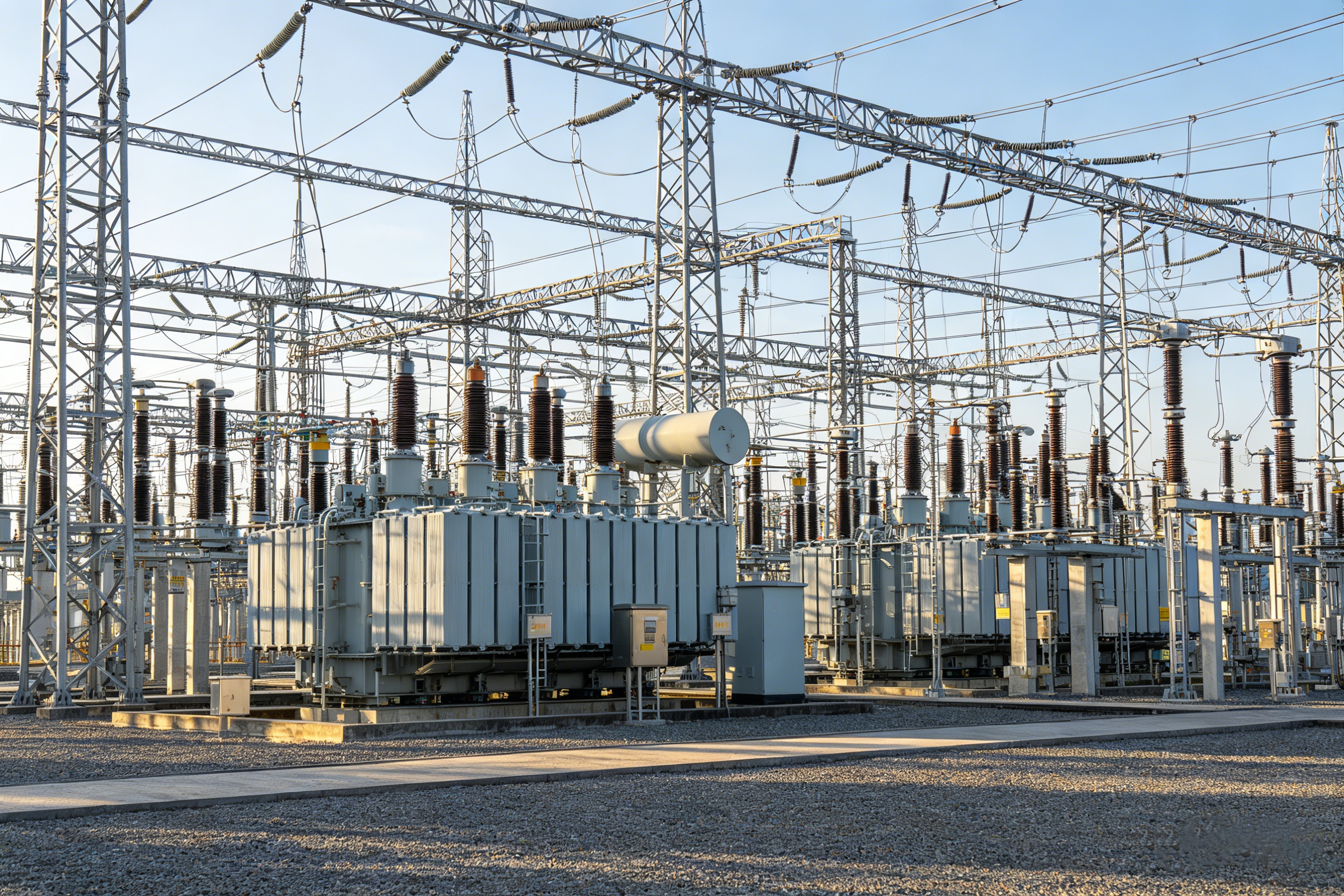
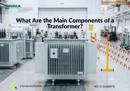
Transformer components are divided into core essential components (common to all transformers) and exclusive accessories for large electric transformerto jointly ensure the insulation, heat dissipation and safe operation of equipment.
Universal core components
- Magnetic core: The mainstream is laminated silicon steel material, and ferrite material is commonly used in high-frequency equipment.The laminated structure can greatly reduce eddy current loss, and the low magnetoresistive characteristics can gather the magnetic field to ensure the efficient transmission of electromagnetic energy.
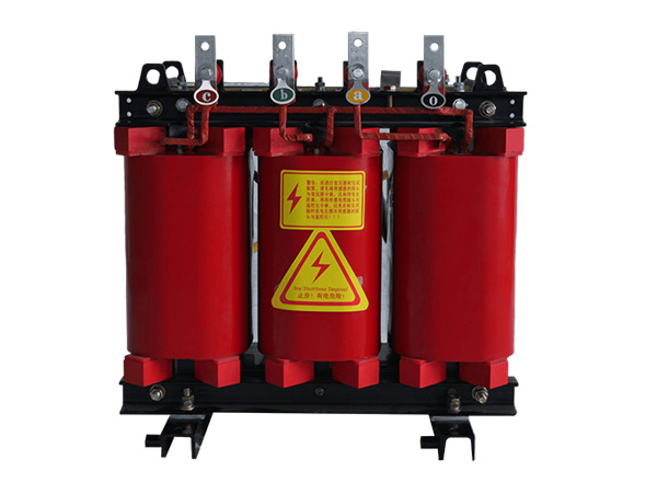
- Primary/secondary winding: it is wound with insulated copper and aluminum enameled wire, which are respectively responsible for accessing the power supply and outputting electrical energy. The number of turns ratio determines the voltage conversion properties of the equipment.
- Insulating medium: it includes insulating paper, insulating paint, epoxy resin, insulating oil, etc., which is used to isolate windings and windings, windings and iron cores, and prevent short circuits and leakage failures. It is the basis for the safe operation of equipment.
Exclusive accessories for high-power transformers
Large-scale oil-immersed transformers for industrial and power grids, with additional functional components, suitable for high-voltage, high-power, and long-term operation scenarios:
- Transformer fuel tank: it adopts a high-strength sealed steel structure shell with excellent overall sealing, which can completely accommodate the iron core, winding and insulating oil, and provide a dust-proof, moisture-proof and corrosion-resistant airtight operating environment for the core components of the equipment.
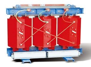
- Insulating oil/dry insulation system: Oil-immersed transformers rely on insulating oil to achieve the dual functions of electrical insulation and circulating heat dissipation to ensure the stable operation of the equipment; dry transformers use air convection with solid resin insulation protection, fireproof and flame-retardant, no fire hazards, and higher operating safety;
- Cooling system: it consists of cooling components such as radiators, cooling fans, and submersible oil pumps, which can quickly divert and dissipate the heat generated by the operation of the equipment, avoid heat accumulation and overheating, and ensure the long-term stable and full-load operation of the transformer.;
- Oil storage cabinet: it can adaptively compensate for the thermal expansion and contraction volume changes of the insulating oil due to temperature changes, and at the same time effectively isolate the invasion of external air and water vapor, avoid oxidation and moisture deterioration of the insulating oil, stabilize the insulation and heat dissipation properties, and extend the service life of the oil.;
- Casing: exclusive high-voltage insulated wiring components, which have the dual properties of reliable conductivity and insulation isolation, can realize the safe connection between the external high-voltage line and the transformer body, effectively eliminate the hidden dangers of creepage, flashover and leakage, and ensure the safety of operation on the high-voltage side.
- Tap switch: the ratio of the number of turns of the winding can be fine-tuned, the output voltage can be accurately calibrated, and the voltage fluctuation of the power grid can be effectively compensated to ensure the stability and compliance of the terminal power supply voltage, and the operation quality of the power grid can be improved.
- Protection device: integrates multiple safety devices such as gas relays, pressure release valves, and temperature sensors to monitor the operating status of the equipment around the clock, and can capture hidden faults such as internal overheating, abnormal oil and gas, and overvoltage in a timely manner, and actively trigger the protection mechanism to effectively avoid equipment damage and electricity safety accidents.
How Does an Electric Transformer Work?
The core of the operation of the transformer is the principle of mutual inductive electromagnetic induction. It follows Faraday’s law of electromagnetic induction and Lenz’s law. It relies on the electromagnetic coupling of the iron core and the two sets of windings to achieve energy transfer, and there is no mechanical movement throughout the process.
Basic core structure
There are only three core working components of all transformers, and the primary and secondary windings are completely electrically isolated, and there is no direct connection with wires.:
- Primary winding (primary winding): Connected to an external input power supply, an alternating magnetic field is generated after energization, which is the excitation terminal of the electromagnetic energy of the transformer;
- Secondary winding (secondary winding): connected to the back-end load equipment, the output voltage is generated by induction of changes in magnetic flux to realize the external transmission of electrical energy;
- Magnetic core (iron core): The mainstream adopts laminated silicon steel material, which can efficiently gather and conduct alternating magnetic fields, greatly reduce magnetic leakage loss, and significantly improve the electromagnetic coupling efficiency of the primary and secondary windings.
Six-step complete workflow
Step 1: Generate alternating magnetic flux
When the AC voltage is smoothly applied to both ends of the primary winding of the transformer, a continuous alternating operating current will be generated in the closed loop.Unlike the constant output characteristics of direct current, the current size, polarity and direction of alternating current will fluctuate and continuously switch with the power frequency waveform.
Alternating current excites the iron core to produce periodic alternating magnetic flux, and a dynamic magnetic field environment is constructed.This is the core prerequisite for transformers to realize electromagnetic induction and energy transmission, and it is also the fundamental reason why they are different from DC static magnetic fields and are only adapted to AC operating conditions.
Step 2: Realize magnetic field coupling conduction
The transformer core is made of high-permeability silicon steel and has very low magnetoresistive characteristics, which can maximize the alternating magnetic flux generated by the primary winding, effectively suppress the phenomenon of magnetic leakage, and reduce the invalid loss of magnetic field energy.
Relying on the directional magnetic conduction of the iron core, the alternating magnetic field can penetrate the secondary winding evenly and stably, realizing efficient electromagnetic coupling on the first and second sides, so that the windings on both sides share the magnetic flux that changes synchronously, and the magnetic field foundation is firmly established for the induction output of stable voltage.
Step 3: inductively generate the output voltage
According to Faraday’s law of electromagnetic induction, when the alternating magnetic flux continues to pass through the closed winding coil, the electromotive force will be induced at both ends of the coil, which is the output voltage of the transformer.The amplitude of the induced voltage mainly depends on the rate of change of the magnetic flux and the number of turns of the secondary winding. The core calculation formula is as follows:
V = -N(dΦ/dt)
Where N is the number of turns of the winding and Φ is the magnetic flux
Step 4: The number of turns ratio determines the voltage level
Under ideal operating conditions, the voltage ratio of the first and second sides of the transformer is strictly equal to the ratio of the number of turns of the winding, and the corresponding formula is:
Vs/Vp =Ns/Np.
According to the difference in the number of turns ratio, transformers can be divided into three categories:
- Boost configuration: The number of turns of the secondary winding is more than that of the primary winding, which can increase the output voltage and adapt to high-voltage and long-distance transmission scenarios.;
- Step-down configuration: The number of turns of the secondary winding is less than that of the primary winding, which can reduce the output voltage and meet the requirements of low-voltage safe power consumption of terminal equipment.;
- Isolation configuration: First, the number of turns of the secondary winding is the same, and the input and output voltages are the same. It is mainly used for circuit electrical isolation to improve the stability and safety of power supply.
Step 5: Power conservation
Under ideal operating conditions, the transformer satisfies the conservation of energy, and the input power is equal to the output power. The formula is: Vp×Ip=Vs×Is.When the power is constant, the voltage is inversely proportional to the current.Combined with Joule’s law, the heat loss of the line is proportional to the square of the current, so the step-up and step-down current can significantly reduce the loss of long-distance transmission, which is the core principle of high-voltage and efficient transmission.
Step 6: Electromagnetic balance
When the secondary winding of the transformer is running with load, a reverse magnetic field will be induced to offset the magnetic flux changes caused by load fluctuations on the primary side, and the input current on the primary side will be adjusted dynamically and adaptively to achieve accurate matching of electromagnetic parameters on both sides.
This autonomous electromagnetic check and balance mechanism is the core of the stable operation of the equipment. It can balance the composite magnetic flux of the iron core in real time, maintain a constant magnetic field throughout the process, effectively avoid magnetic field disorders, voltage fluctuations and other problems, and ensure the smooth and reliable operation of the transformer under various load conditions.
Why Are Electric Transformers So Efficient?
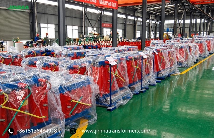
Transformers are currently one of the most energy-efficient electrical equipment. The energy efficiency of ordinary electric transformercan reach 95%-99%, and the energy efficiency of large high-voltage transformers even exceeds 99.7%. There are four core reasons.:
- No mechanical loss: Transformers are static power equipment and do not contain any moving components such as motors, bearings, and brushes. There is no mechanical friction and rotational loss during operation. The loss of the whole machine is only derived from trace electromagnetic losses, and the innate energy efficiency advantages are outstanding.
- Both types of core losses can be optimized by mature processes: the core loss is derived from hysteresis and eddy current, and the thin laminated structure of high-purity silicon steel can be effectively reduced, and the loss is not affected by the load and is basically constant; the copper loss of the winding is caused by the heating of the wire resistance. By selecting high-conductivity wire and optimizing the wire diameter, the current and heat loss can be significantly reduced.
- Extremely high electromagnetic coupling efficiency: the high-conductivity magnet core can gather more than 99% of the magnetic flux, and the magnetic leakage is extremely low. Almost all the electromagnetic energy of the primary winding is transmitted to the secondary winding, and there is very little energy loss.
- Mature design: The transformer only realizes electromagnetic energy transfer and cannot be converted in the form of energy. Relying on a century-old mature technology, high-quality materials and precise heat dissipation design, the energy efficiency of long-term operation is stable without significant attenuation.
What Causes Transformer Energy Losses?
The ideal transformer can realize lossless transmission of electrical energy and is only suitable for theoretical research.In actual operation, due to the deviation of materials, processes and electromagnetic coupling, transformers will produce trace heat loss, which is the main reason for the decline in heat generation and energy efficiency of equipment. The losses are mainly divided into two categories.
Core loss
The iron core loss (iron loss) is a fixed loss, which is generated when the equipment is energized. It has nothing to do with the size of the load, and it still exists under no-load conditions.It mainly includes hysteresis loss and eddy current loss: The alternating magnetic field repeatedly magnetizes the iron core, which will produce hysteresis loss due to the friction of magnetic molecules.
The alternating magnetic flux induces an eddy current inside the iron core, and the eddy current loss is formed by relying on the resistance of the iron core to generate heat.The high-purity thin-laminated silicon steel core is used in the project, which can effectively suppress two types of losses and reduce the iron loss value.
Winding copper loss
The copper loss of the winding is a variable load loss and is the main source of loss for the operation of the equipment with load.There is inherent resistance in the winding wire, and when the load current flows through the coil, I2R heat loss will be generated according to Joule’s law. The size of the loss increases in square order with the increase of the load current, which is most significant under heavy-duty conditions.By using high-conductivity wire and optimizing the winding diameter and winding length, the winding resistance can be effectively reduced, copper loss can be reduced, and equipment heat generation can be reduced.
Other trace losses
Trace auxiliary losses include magnetic leakage loss, insulating dielectric loss, mechanical vibration loss, etc.A small amount of leakage of magnetic flux, high-voltage polarization of insulating materials, and electromagnetic micro-vibration of iron core windings will produce a very small amount of energy loss, and the overall proportion is extremely low. It has almost no effect on the energy efficiency and temperature rise of the transformer, and there is no need to consider it under conventional operating conditions.
How to Choose the Right Electric Transformer
Scientific selection is the key to the long-term, efficient and safe operation of transformers. It needs to be matched in multiple dimensions such as load, working conditions, environment, and standards to avoid overload, inefficiency, and safety hazards.
Approved rated capacity
The rated capacity is the primary core parameter of transformer selection, which directly determines the carrying capacity of the equipment and the operating safety margin.When selecting the type, it is necessary to count the total load active power of all electrical equipment on the site, and calculate the rated capacity of the transformer based on the system power factor.;
When there is no accurate power factor data, the industry’s unified value is 0.8; 20%-25% capacity margin needs to be reserved to withstand start-up shocks and adapt to later expansion.It is strictly forbidden to select models at full load and overload to avoid overheating, aging, short circuit and burning of equipment.
Matching voltage parameters
Voltage parameter adaptation is the basic prerequisite to ensure the normal power supply of equipment and prevent operating failures.The input voltage of the primary side of the transformer must strictly match the power supply standards of the on-site power grid, and adapt to the conventional high-voltage and medium-voltage power supply levels in the area to avoid voltage mismatches that cause the equipment to fail to work properly.
The output voltage of the secondary side needs to match the rated parameters of the load to ensure the stable operation of the equipment.Step-up, step-down or isolation transformers can be selected according to working conditions, which are suitable for long-distance transmission, terminal power distribution, and precision equipment isolation scenarios.
Number of power supply phases
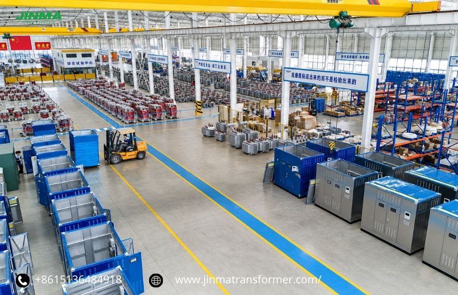
The number of power supply phases is divided into single-phase and three-phase according to the load power and scene selection.The single-phase transformer has a simple structure and easy operation and maintenance. It is suitable for civil low-power and light-load scenarios such as homes, shops, and lighting.
The three-phase transformer has large power supply capacity, strong output stability, and excellent carrying performance. It can achieve high-power continuous power supply and effectively avoid the problem of three-phase voltage imbalance. It is widely used in industrial production machinery, large public buildings, urban backbone power grids, high-power precision equipment and other high-power, continuous electric field scenarios.
Operating frequency
Transformers are special equipment for frequency adaptation, and the operating frequency must exactly match the rated frequency of the regional power grid. The general domestic standard is 50Hz, and some imported equipment and foreign-related working conditions are 60Hz.
If the frequency of the equipment does not match the frequency of the power grid, it will directly cause magnetic saturation of the iron core and a sharp increase in eddy current loss, resulting in abnormal heat generation of the equipment, insufficient output power, voltage waveform distortion and other problems. In severe cases, it will lead to frequent equipment failures, downtime and burning. Therefore, the frequency parameters must be strictly checked during the selection stage to ensure that the working conditions are adapted.
Working conditions and environment
Transformers need to be selected according to site environment and safety standards: hospitals, shopping malls, data centers and other indoor fire-resistant harsh scenarios, suitable for safe and maintenance-free dry transformers;
Oil-immersed transformers with good heat dissipation and large capacity are selected for outdoor high-voltage, heavy-duty and long-term operation conditions; toroidal transformers with low noise, high efficiency and compact size are suitable for small spaces and precision silent equipment scenarios.
Follow energy efficiency standards
Transformers are long-life power equipment with a service cycle of up to 30-40 years. The energy efficiency level directly determines the operating cost of the whole life cycle.When selecting models, priority should be given to high-efficiency and energy-saving models that meet the domestic national standards and international authoritative certifications such as IEC and IEEE.
The initial procurement cost of energy-efficient transformers is slightly higher, but the iron loss and copper loss are lower, the operating temperature rise is small, the stability is strong, the energy consumption and operation and maintenance costs of the whole life cycle are lower, and the comprehensive benefits and reliability are significantly better than ordinary models.
Adapt to installation conditions
The selection of the type needs to fully consider the on-site installation and environmental limit conditions, so as to avoid the problems of equipment capacity reduction and frequent failures caused by special working conditions.Combined with the altitude of the site, the changes in temperature and humidity in the four seasons, the degree of air corrosion, and the requirements of seismic fortification, the installation form of the transformer is determined, including pole installation, floor pre-installation, cabinet installation, etc.
At the same time match the corresponding cooling and cooling scheme.In harsh environments such as high altitude, high temperature, high humidity, and dust, the insulation performance and heat dissipation efficiency of the equipment will decrease slightly. The power reduction margin needs to be reserved in advance to avoid overheating and insulation failure when the equipment is running at full load, and to ensure long-term stable operation in complex environments.
Special function configuration
Combined with the working conditions and load characteristics of the power grid, special functional accessories can be selected in a targeted manner to improve the adaptability and operating stability of the equipment.For areas where the voltage of the power grid fluctuates frequently, tap switches can be installed to accurately fine-tune the voltage ratio, compensate for the voltage difference of the power grid, and ensure the stability and compliance of the output voltage.
High-harmonic loads such as frequency converters and computer rooms need to be equipped with anti-harmonic transformers to reduce harmonic loss, heat generation and equipment interference; high-end loads such as medical and precision instruments can be equipped with shielding, noise reduction, intelligent monitoring and other configurations to achieve stable operation with high precision and low interference.
Conclusion
Electric transformeruse electromagnetic induction and the ratio of winding turns to achieve voltage regulation and voltage transformation. With ultra-low loss characteristics, they have become the core equipment of power systems and are widely used in power transmission and distribution, industrial and civil power supply scenarios.Mastering its principle, type and selection method can accurately adapt to working conditions, save energy and reduce consumption, reduce equipment failures, and reduce operation and maintenance costs.