

Selecting the appropriate industrial voltage regulator is a frequent yet highly error-prone task in electrical engineering. If the capacity is too small, the voltage regulator is prone to overload tripping or even component burnout during motor startup; if the capacity is too large, it results in unnecessary waste of procurement costs and operational energy consumption.
The most reliable basis for determining the capacity of a voltage regulator is the often-overlooked plant load list. This list records the power, current, load type, starting method, and operating conditions of downstream equipment, serving as the foundation for capacity conversion, inrush compensation, and voltage matching. Missing or distorted data in the checklist is a primary cause of on-site tripping of voltage regulators.
This article takes the factory load list as its core, breaking down the entire process from load analysis and capacity calculation to inrush current compensation and equipment selection, and includes practical examples to help engineers quickly complete a scientific and cost-effective selection.
Understand the Factory Load List and Its Electrical Requirements
Difference between connected load and maximum demand load
The list must distinguish between connected loads and maximum demand loads. The connected load is the sum of the nameplate power of all electrifiable equipment, representing the maximum potential power consumption capacity; the maximum demand load is the maximum load that actually operates simultaneously under real emissions. For standardized management plants, the simultaneous factor usually depresses the simultaneous load to 60% to 80% of the arithmetic sum.
Convert power to apparent power (kVA)
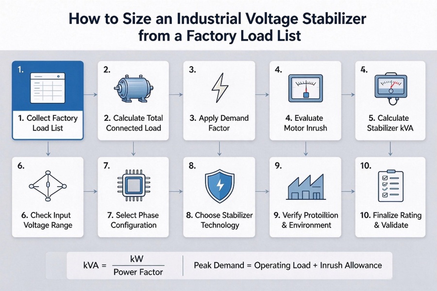
Regulator is rated in kVA (apparent power) rather than kW (active power). The conversion formula is: kVA = active power kW ÷ power factor. A typical industrial mixed load (motor and electronics) has a power factor between 0.75 and 0.85, and a purely resistive heating device is close to 1.0. When the current and voltage are known, single-phase kVA = (phase voltage × phase current) ÷ 1000, and three-phase kVA =(√ 3 × line voltage × line current) ÷ 1000.
Electrical Design Elements Revealed by the Load List
In addition to the total capacity, the list also reveals four key electrical characteristics. First is the inrush and starting current: induction motors typically draw 3 to 6 times their rated current upon direct start, with some designs reaching 7 to 8 times; the voltage regulator’s correction components and overload capacity must withstand the maximum simultaneous starts without tripping or losing stability. Using soft starters or variable frequency drives can reduce this to 1.5 to 2.5 times.
Second Phase number configuration and balance: Unbalanced single-phase loads on the feeder may require phase-by-phase independent voltage regulation. Third, harmonics and nonlinear loads—frequency converters and CNC systems will inject harmonics and increase heat generation. Fourth, continuous versus intermittent operating conditions: continuous production lines have much higher thermal margin requirements than intermittent equipment.
Calculate the Total Connected Load
After reading the list, it needs to be translated into a concrete numerical basis-the total connection load. The method is to list the rated power of each equipment item by item (HP is converted into kW,1HP is about 0.746kW), add all together to obtain the total connected load kW, and divide it by the aggregate power factor to obtain the total connected kVA. It should be emphasized that the original connection kVA is only a starting point for the calculation, not a final rating.
Industrial example
Equipment of a factory is 20kW of numerical control machine tool, 15kW of air compressor, 10kW of packaging line, 5kW of lighting control, and the total connection load is 50kW. According to the power factor 0.8, 50 ÷ 0.8=62.5kVA. This value is only connected to the apparent capacity, but also needs to enter the demand factor and impact compensation link.
Determine the Actual Operating Load and Demand Factor
Definition of Demand Factor
The arithmetic sum of the connected loads hardly occurs at full load at the same time in actual production. The demand coefficient refers to the ratio of the actual maximum demand to the total connected load, which is always less than or equal to 1.0, and the typical industrial value is 0.60 to 0.85. Therefore, actual operating load (demand load) = connected load × demand factor.
Three Methods of Obtaining Actual Operating Load
Method 1 is the measured peak demand method, suitable for commissioned plants. It uses meter interval data (15 or 30 minute peaks), energy meter logs, or temporary power analyzers recorded during representative production periods, accurately reflecting simultaneity, partial load factors, and seasonal variations.
Method 2 is calculation by list, suitable for new projects or scenarios lacking measured data. It involves applying demand factors separately to each equipment category and then summing them: large continuous-process motors 0.75 to 0.90, intermittent motors 0.70 to 0.85, HVAC compressors 0.85 to 0.95, LED lighting 0.95 to 1.0, and critical or UPS loads 1.0.
Method three is simultaneous operation and scheduling analysis, which involves verifying shifts against equipment that does not operate concurrently and recording the most unfavorable simultaneous combinations. For example, with a connected load of 110kW and an overall demand factor of 0.73, the actual operating load is approximately 80 kW, which corresponds to about 92kVA when converted based on a power factor of 0.87.
The difference between the required coefficient and the simultaneous coefficient.
The two are often confused. The demand coefficient (≤ 1) describes the ratio of the maximum demand of a load to the connected load, while the coefficient (≥ 1) is the ratio of the sum of the individual maximum demand of each load to the combined maximum demand in the same period. In the project, the demand coefficient is usually applied directly to the total amount of connections. If the coefficient is superimposed at the same time, it will be repeatedly reduced, resulting in a small selection.
Account for Motor Starting Currents and Other Inrush Loads
Motor start-up shock is the number one cause of industrial voltage regulator start-up trip. Only according to the steady-state operation load selection, almost inevitably in the large motor power-on instantaneous failure; The regulator must be in a short strong current spike safely through, neither overload protection misoperation, nor let the output voltage drop.
Source of impact load
The rotor speed of the induction motor is zero at the moment of closing, the back electromotive force is not established, the locked-rotor current directly started usually reaches 5 to 8 times of the full load current, and the design of the high-efficiency motor can reach 6 to 10 times, lasting for hundreds of milliseconds to several seconds. However, the correction element, contactor and heat capacity of the voltage stabilizer must be able to withstand. In addition, the transformer excitation shock (often up to 8 to 15 times), welding equipment and large capacitors or compensation cabinet, is also the need to capture the impact of the source.
Impact multiples of different start-up modes
In actual calculation, it is only necessary to apply the corresponding starting mode multiple to the motor part, and the non-motor load remains the original value. The impact multiple and the practical multiplier of the regulator corresponding to each mode are shown in the table below.
| Startup method | Typical starting current | Voltage regulator utility multiplier (for motor kVA) | Description |
| Direct Start (DOL) | 5~8 times full load current (up to 10 times) | 2.5~5 times (commonly used 3~4 times) | Demand is highest and must be clearly documented |
| Star Triangle Start | About 2~3 times full load current | 1.8~2.5 times | Starting torque decreases synchronously |
| Soft starter | 2~4 times (can be set) | 1.3~2 times | Controllable start slope |
| Frequency Converter (VFD) | About 1~1.5 times full load current | 1.2~1.5 times | The impact of the shock is minimal. |
The above multiplier is taken from the engineering practice of pressurizer selection and has taken into account the short duration of the impact. The practical algorithm is to take the kVA of the motor part multiplied by the multiple of the starting mode, and then add the non-motor load by 1.0 times the original value, and the sum of the two is the instantaneous peak value that the voltage stabilizer must support.
For example, if the actual operation is 80kVA, of which 60kVA is a direct start motor, then 60 × 3.5+20 = 230kVA (this is before margin addition). If multiple large motors can be started at the same time, it is calculated as the most unfavorable combination at the same time.
Reduce the impact on the selection
Installing a soft starter or frequency converter on the load side is the most effective engineering method to reduce the required capacity of the voltage stabilizer. The starting method of each motor must be specified when inquiring. The blocking current of the new generation of high-efficiency motors is often higher, and the manufacturer’s data should be verified if conditions permit.
Convert the Factory Load into the Required Stabilizer Capacity
Core conversion formula
Calculation results of the previous links converge to the number that the regulator must be rated to carry, which is a comprehensive part of the selection. The standard formula is: required capacity kVA = (actual operating load kW ÷ power factor) × safety margin; When the impact has been applied to the motor part in advance, it can also be written as: required capacity kVA = peak demand with impact kVA × (if additional margin is required).
Common engineering values: mixed load power factor 0.75 to 0.85 (unknown according to conservative 0.8); After the impact has been included, the safety margin of mixed load with clear starting mode is 1.20 to 1.30. For factories with high motor proportion and high impact multiple (2 to 3 times or more), the overall margin can be narrowed to 1.15 to 1.25.
Step-by-step conversion process
Step 1: Determine the actual operating load in kW.
Step 2: Convert this to base kVA using the true power factor.
Step 3: Apply a peak demand correction factor—multiply by the appropriate starting multiplier for motor loads and by 1.0 for non-motor loads.
Step 4: Further increase the peak value by 20% to 30% to provide a final safety margin, accounting for measurement uncertainty, derating due to environmental conditions, and future growth.
Step 5: Round up to the next standard rating (e.g., 10, 25, 50, 100, 250, 500 kVA, etc.).
Complete example
Taking an actual operating load of 80kW with a power factor of 0.8 as an example: the base capacity is 80 ÷ 0.8=100 kVA; for the motor portion, 60kVA is multiplied by 3.0 for direct-on-line starting, resulting in 180 kVA, while the non-motor portion is 20 kVA, yielding a peak demand of 200 kVA; multiplying this by the final safety margin of 1.25 gives a total of 250 kVA.
When selecting components, it is also necessary to verify that the selected rated values can deliver full capacity at the lowest expected input voltage, as the current will increase when the voltage drops. Never select equipment strictly according to calculated values; always choose the next higher standard rating—although the cost difference is minimal, the risk of tripping and production shutdowns can be vastly different.
Check Input Voltage Fluctuations and Stabilization Range
Actual measured input range at the site
If the capacity is sufficient, if the input window cannot cover the actual voltage fluctuation of the installation point, the selection is still invalid. It shall be measured at the actual point of connection of the regulator (after the upstream transformer or long feeder), without relying on the nominal grid voltage or supply commitments. It is recommended to use a voltage recorder or power quality analyzer to record continuously for 7 to 14 days, covering peak shifts and the most unfavorable seasons, focusing on recording the absolute maximum and minimum values of line-to-line voltage, the frequency of sags and sags, and the phase-to-phase imbalance.
Voltage deviation calculation
Voltage deviation (%)= (measured voltage-nominal voltage) ÷ nominal voltage × 100%. For example, 400V nominal system measured extreme value 320V to 460V, the corresponding deviation is-20% to + 15%. This interval is the input basis for voltage stabilization range matching.
Selection principle of voltage stabilizing range
Models shall be selected where the input window clearly covers the measured extremes and allows for a practical margin. Rule of thumb: at least 15% or 20% is selected when the measured fluctuation is within 12%; Select 25% or 30% wide range models when 18% to 20%; Industrial or rural power grids with poor power supply quality often need 30% or asymmetric range.
Taking the three-phase 380/400V nominal as an example, the standard range is about 15% to 20%, and the wide range is about 25% to 30%. Once the input is out of the rated window, the excess will directly penetrate to the output or the whole machine will be bypassed. It is also necessary to confirm that the regulator can still output full kVA at the lowest input voltage, and to separate the input range and output accuracy (servo or IGBT models are usually better than 1%).
Select the Correct Phase Configuration and Output Specifications
Selection of phase configuration
Single-phase voltage stabilizers are intended only for applications where the entire protected circuit is single-phase (typically 220/230/240V two-wire system), making them suitable for small workshops, individual equipment, or standalone control cabinets with a capacity of 10 to 15kVA or less. Three-phase voltage stabilizers are essential for industrial equipment equipped with three-phase motors, CNC machines, air compressors, production lines, or main distribution cabinets, as single-phase devices cannot correct line-to-line voltage imbalances or phase unbalance.
Three-phase transformers also need to be distinguished between phase-by-phase independent voltage regulation and three-phase unified voltage regulation. Phase-separated independent voltage regulation involves sampling and correcting each phase separately, which is particularly necessary when single-phase loads are unevenly distributed across the three phases, the power supply itself is unbalanced, or large motors are started on a specific phase combination. In contrast, three-phase unified regulation employs a single control loop for all three phases, resulting in a more cost-effective design, but it is only suitable for applications where the power supply and load remain relatively balanced at all times. When requesting a quotation, please specify whether phase-separated independent voltage regulation is required, and confirm whether the wiring is three-wire or four-wire with a neutral conductor.
Output parameter specifications
Nominal output voltage, I .e. the voltage actually required by the load (e. g. 400V between lines), must be specified. Secondly, the output voltage stabilization accuracy, numerical control, PLC, servo, medical or precision process equipment requires 1% or better, general motor and mixed load can be 2% to 3%, only non-critical resistive load is allowed 5% or wider.
It is also necessary to clearly correct the response speed (servo is about 10 to 50V per second, static IGBT is faster). If phase-splitting independent voltage regulation is specified, it is confirmed to have 100% unbalanced load bearing capacity, and overload and short-time overload ratings are declared to cover the impact peak.
Evaluate Load Characteristics and Stabilizer Technology
Dimensions for evaluating load characteristics
Correct technical approach is determined by the nature of the load, not solely by price.
First, classify the protected loads: one is their sensitivity to voltage deviation—CNC machines, PLCs, servos, medical imaging equipment, and semiconductor devices typically require ±1% or tighter tolerance, while general motors, pumps, and lighting can tolerate ±2% to 3% or even wider; the other is the response speed requirement—fast electronic loads that trip due to brief voltage dips need millisecond-level correction, whereas heavy motor loads with large thermal inertia can accept correction within 1 to 2 seconds.
Third is the impact and harmonic content: high motor starting currents and inverter harmonics favor electromechanical or static solutions with strong overload capacity. Fourth is the operating cycle and environment: all-weather continuous operation, high dust levels, or maintenance constraints influence the choice between electromechanical and solid-state designs.
Mainstream regulator technology comparison
| Technology type | Typical accuracy | Response time | Maintenance Requirements | Optimum Load | Main limitations |
| Relay/contact voltage regulation | ±5%~8% | Less than 50ms (step) | low | Lighting, simple HVAC, non-critical pumps, budget applications | Step correction, limited capacity, not suitable for precision electronics |
| Servo Electromechanical | ±0.5%~3% | 10~50 ms/V, about 1~2s | Regular brush holder and motor maintenance | Most industrial motors, CNC, air compressors, mixing production lines, packaging | Mechanical wear, slower than static during ultra-fast drop |
| Static / IGBT‑based | ±0.5%~1% | Less than 10~20ms (often sub-cycle) | Very low (brushless) | High-precision CNC, medical, semiconductor, data center, sensitive electronics, critical loads | Highest cost, more sensitive to extreme environments |
Decision recommendation: Servo electromechanical type is the main force of most factory applications, taking into account sufficient accuracy, can be extended to thousands of kVA tolerance range, strong overload capacity for motor impact and mature and reliable at medium cost. The IGBT/static type is selected when the load is tripped due to a short drop, the requirement of ± 0.5% accuracy or zero mechanical maintenance is a hard requirement.
Verify Protection, Installation, and Environmental Requirements
Essential protection features
As required, the following functions shall be either standard features or explicitly listed options: overload and short-circuit protection, with time-delayed overload characteristics (e.g., 125% for 1 minute, 150% for 10 seconds) to withstand motor inrush currents while promptly interrupting short circuits; overvoltage/undervoltage shutdown, automatically disconnecting or switching to bypass when the input voltage exceeds the correction window, with adjustable thresholds.
Phase-loss, phase-sequence, and unbalance protection are essential for three-phase models; bypass options include manual maintenance bypass and a preferred automatic bypass, enabling uninterrupted production when the voltage stabilizer is isolated. In addition, surge/transient protection must be provided by installing Class I/II surge protectors at both the input and output terminals, as voltage regulators cannot replace surge protection; overheat/over-temperature protection should also be included; and circuit breakers or molded-case switches that are properly matched to the cable and load capacity must be installed.
Installation and Environmental Rating
Regarding installation, the voltage regulator should be placed indoors in a dry, level, and load-bearing location, with a clear clearance of 600 to 1,000mm around all sides for ventilation and maintenance. For air-cooled models, ensure unobstructed air intake and exhaust; never block the inlet and outlet grilles. Select cable sizes appropriately based on current ratings, ensure proper torque at the terminals, and reliably connect the neutral and grounding conductors; for phase separated, independently regulated models, the neutral conductor must be securely connected. Equip the system with upstream and downstream disconnect switches and a clearly labeled bypass path. Before handover, verify the input and output voltages, phase sequence, protective settings, and full load temperature rise.
The environmental rating must match the site conditions: The standard ambient temperature range is typically −10°C to +40/45°C; higher temperatures require derating or enhanced heat dissipation. For altitude, equipment is generally rated at full capacity up to 1,000–1,500 meters; above this, derating should be applied according to the manufacturer’s derating curve (typically about 1% per 100 meters increase). Humidity should be managed to prevent condensation, usually up to 90%–95% relative humidity.
Regarding ingress protection, electrical rooms within cleanrooms may use IP21 or IP23; areas with dust, outdoor environments, or washdown zones require IP54 or higher, and outdoor enclosures should be installed where necessary. If conductive dust, chemical mists, or salt spray are present, a higher protection rating or a specialized coating should be specified. At the same time, confirm compliance with relevant standards and develop maintenance plans that include visual inspections, dust removal, and functional tests for protective measures.
Finalize the Stabilizer Rating and Validate the Selection
Final integrated specification list
All the above calculations and decisions converge to a clear rating specification that can be placed directly and accepted on site, and are organized into a one-page specification table: required kVA (including impact peak value × final margin and rounded up), input voltage window, output voltage and accuracy, phase number configuration, technical route, protection and function, and environmental level. This specification sheet is the common basis for the purchase order and the factory acceptance criteria.
Pre-order verification and post-installation acceptance
Before placing the order, cross-check the final kVA rating against the original load list, demand factor, and inrush current calculations; confirm that the manufacturer’s published input range fully covers the measured peak values under full-load conditions; request the overload–time characteristic curves to verify that they can accommodate the simultaneous starting of the largest motors; and review the single-line diagram and protective device settings, obtaining either the factory acceptance test (FAT) procedures or prototype test reports that demonstrate the voltage regulation accuracy.
After installation is complete, measure the input and output voltages under three operating conditions: no-load, normal production load, and maximum motor start-up, and verify that the output remains within the specified accuracy range; test all protection functions; verify temperature rise, ventilation, and grounding; record the final setpoints and archive them.
There is no unchangeable universal formula for the selection of industrial voltage stabilizer, but it follows a clear and reproducible logical main line: starting from the load list, converting the nameplate power into the apparent capacity, restoring the real operating load with the demand coefficient, checking the peak capacity with the starting impact, matching the voltage range, phase number configuration, technical route and protection installation elements, and finally converging into a clear rated value that can be purchased and accepted, the whole process runs through the principle of “measurement priority, reasonable margin and standard gear nearby.
As long as the data is complete and the steps are rigorous, the voltage regulator can output stably under full load and the worst start-up conditions, providing long-term and reliable voltage guarantee for factory production.