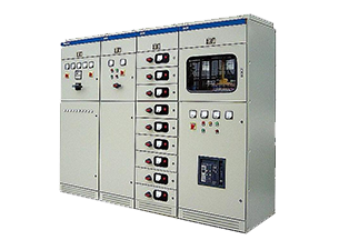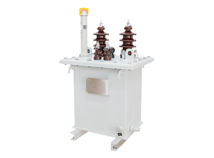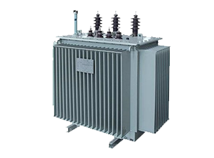


In the construction of photovoltaic power plants, the selection and procurement of transformers and switchgear directly impact project quality, power generation efficiency, and long-term operational performance over a 25-year period, making them a core focus of EPC project management. Photovoltaic power plants operate under complex and unique conditions, characterized by intermittent power generation, significant harmonic distortion from inverters, and frequent load fluctuations. Furthermore, as they are exposed to harsh outdoor environments over the long term, standard distribution transformers struggle to meet the demands of long-term, stable operation. Currently, most solar projects face issues such as low power generation, frequent equipment failures, difficulties in grid connection acceptance, and excessively high O&M costs. The root causes of these problems largely stem from non-standardized equipment selection and unreasonable parameter matching during the preliminary planning phase.
Drawing on hands-on experience from frontline PV engineering projects, this article systematically explains the core value of PV transformers, equipment categories, the selection process, key parameters, project pain points, scenario-based solutions, compliance standards, and supplier selection techniques. It provides EPC contractors with a practical procurement and selection guide to facilitate compliant grid connection, improve quality, reduce costs, and enhance long-term investment returns for PV projects.
The Role of Transformers in Solar Power Plants
The Core Hub of Photovoltaic Power Transmission
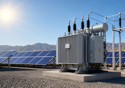
Transformers serve as the core hub of photovoltaic grid-connected systems. The low-voltage direct current (DC) output from photovoltaic modules is converted by inverters into low-voltage alternating current (AC), which cannot meet the requirements for long-distance, low-loss power transmission. Therefore, the voltage must be stepped up in stages via step-up transformers to facilitate power aggregation and grid-connected transmission; transformers are thus essential core equipment for the operation of power plants. During operation, the step-up transformers at the inverter stations in the array areas are responsible for converting low voltage to medium voltage and aggregating power on-site, while the central main transformer steps up the medium voltage to high voltage to enable long-distance grid connection.
Layout Logic for the Three Major Types of Photovoltaic Transformers
Transformers in photovoltaic power plants are divided into three major categories: inverter step-up transformers, main grid-connection transformers, and auxiliary station transformers. These three types of equipment differ significantly in function, installation location, and applicable scenarios; EPC contractors must select and configure them specifically based on the plant’s scale and cannot use them interchangeably.
Inverter step-up transformers are distributed throughout the photovoltaic array area, connecting directly to inverters for step-up and power collection, and are suitable for all distributed and centralized photovoltaic projects. Main power transformers are centrally deployed in the step-up substation, where they consolidate and step up the power from the entire plant for grid connection. They serve as the core grid-connection equipment for large and medium-sized ground-mounted and commercial/industrial PV projects. Auxiliary transformers are part of the plant’s O&M support infrastructure. Installed within the step-up substation, they provide continuous low-voltage power to systems such as the central control room, communications, cooling, security, and tracking mechanisms, ensuring that the plant’s O&M systems continue to function normally even when PV generation is suspended.
Functional Differences Between Step-Up Transformers and Auxiliary Transformers
Step-up transformers and auxiliary transformers serve distinctly different functions; their interchangeability is strictly prohibited during procurement and construction. Step-up transformers are core power generation equipment, primarily serving to step up voltage for transmission, reduce line losses, isolate electrical circuits, suppress harmonics, and stabilize voltage, thereby ensuring efficient power generation and compliant grid connection for the power plant.
Auxiliary transformers are supporting equipment whose core function is medium-to-low voltage step-down, converting grid voltage to 400V low voltage to power auxiliary equipment within the plant. These transformers can operate independently of the grid and possess fault isolation capabilities, ensuring the uninterrupted operation of critical plant equipment.
Transformer Efficiency Determines Long-Term Project Returns
Over the 25-year operational lifespan of a photovoltaic power plant, transformer efficiency directly determines the cost per kilowatt-hour and the project’s return on investment. Transformer losses are divided into fixed no-load losses and dynamic load losses. While ordinary, low-cost transformers require a lower initial investment, they consume electricity continuously over the long term and result in significant energy losses, which can substantially reduce the project’s overall returns.
Types of Transformers Used in Solar Power Plants
Inverter-Specific Transformers (IDT)
IDT inverters are the most widely used core equipment in photovoltaic projects. They are specifically designed for the nonlinear, high-harmonic, and frequently varying load conditions of inverters and cannot be replaced by standard power distribution transformers. Standard transformers are only compatible with standard sinusoidal grid power. When subjected to the high-frequency PWM harmonics from inverters over extended periods, they are highly prone to issues such as overheating, insulation degradation, soaring power losses, and a drastically shortened service life.
IDTs utilize harmonic-resistant cores and optimized winding structures, making them suitable for the intermittent power generation conditions typical of PV systems and ensuring greater stability during long-term partial-load operation. The conventional low-voltage side is compatible with the outputs of mainstream inverters rated at 400 V, 690 V, and 800 V, while the high-voltage side is compatible with 11 kV and 33 kV medium-voltage collection systems; the Dyn11 vector group effectively suppresses zero-sequence current and optimizes ground fault protection.
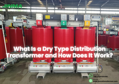
Outdoor pad-mounted and skid-mounted IDTs are suitable for ground-mounted PV power plants; their high IP protection rating enables them to withstand high temperatures, dust, and rain. Dry-type IDTs are fire-resistant and low-noise, making them suitable for commercial and industrial rooftops as well as enclosed indoor environments. Multi-winding models can connect to multiple inverters simultaneously, effectively reducing the capital expenditure per watt.
Medium-Voltage Step-Up Transformers
Medium-voltage step-up transformers are primarily used for the secondary collection and step-up of electrical energy from PV arrays. They receive the output power from distributed IDTs, consolidate it, and feed it into the main step-up substation, making them suitable for commercial and industrial as well as large-scale ground-mounted PV projects. Equipment capacity typically ranges from 1 to 5 MVA, and capacity can be expanded by connecting multiple units in parallel; the voltage ratio is primarily from 0.4 kV to 11–35 kV.
The equipment features optimized partial-load efficiency to address the characteristics of photovoltaic systems—such as low loads and significant fluctuations—making it suitable for low-light conditions in the morning and evening, as well as low-output conditions on cloudy days. Oil-immersed models offer excellent heat dissipation, strong load-carrying capacity, and high cost-effectiveness, making them the preferred choice for large-scale outdoor photovoltaic arrays; dry-type models pose no risk of oil leakage, are fire-safe, and are easy to maintain, making them suitable for environmentally sensitive areas such as industrial sites, rooftops, and densely populated areas.
Main Grid-Connected Transformers
Main transformers are the core grid-connection equipment for large-scale photovoltaic power plants. Located in central step-up substations, they are responsible for stepping up 33 kV medium-voltage power to high-voltage levels of 66 kV, 110 kV, or 220 kV to meet the requirements for long-distance, low-loss grid transmission. The equipment must feature high capacity, high stability, and strong voltage regulation capabilities to withstand full-load surges across the entire plant and fluctuations in grid voltage.
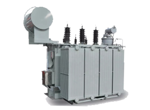
The mainstream models are large-capacity oil-immersed transformers equipped with ONAN/ONAF dual-mode cooling systems, designed for high-temperature, full-load operation. They come standard with OLTC on-load tap changers, which enable real-time dynamic voltage regulation to meet grid interconnection standards. Large-scale power plants often employ a dual-main-transformer redundancy design to minimize the risk of downtime and ensure continuous grid connectivity.
Station Auxiliary Transformers
Auxiliary transformers are standard equipment for the entire station, typically ranging in capacity from tens to hundreds of kVA. Their primary function is to step down the 10 kV/35 kV medium voltage to 400 V low voltage, supplying power to station equipment such as monitoring, communication, cooling, lighting, security, and tracking motors. These devices must operate stably 24 hours a day, unaffected by the start-stop cycles of photovoltaic power generation. When selecting and procuring these transformers, priority is given to low noise, high stability, and maintenance-free characteristics to reduce long-term operation and maintenance burdens.
How to Select the Right Transformer for a Solar Project
Selecting Models Based on Power Plant Scale
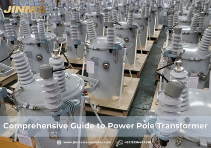
Operating conditions vary significantly among PV projects of different installed capacities, so EPC contractors must match equipment to specific needs to avoid under-capacity or excessive redundancy. Residential PV systems, typically ranging from 10 to 20 kW, are relatively small and often use inverter-integrated transformers or small pole-mounted transformers, prioritizing compact size, low noise, maintenance-free operation, and compatibility with residential power grids.
Commercial and industrial (C&I) PV projects, ranging from 100 kW to 5 MW, are primarily rooftop and on-site distributed projects. These typically use small- to medium-sized PAD-type outdoor transformers or indoor dry-type IDTs, balancing harmonic tolerance, fire safety, and space requirements while flexibly accommodating string inverter layouts.
For ground-mounted power plants of 5 MW or more, a “distributed IDT + centralized main transformer” combination model is adopted. Multi-winding IDTs with capacities of 1–10 MVA are deployed in the array area to collect power by zone, while the step-up substation is equipped with a high-capacity main transformer for high-voltage grid connection. Selection criteria prioritize high efficiency, energy savings, environmental adaptability, grid compliance, and room for future expansion.
Precise Matching Across Three Voltage Levels
Voltage matching is fundamental to equipment selection; parameter deviations can directly lead to low efficiency, equipment malfunctions, or even burnout. The low-voltage side must strictly match the inverter’s 400V, 690V, and 800V output levels; the medium-voltage busbar side uses 11 kV or 33 kV (adapted to 22 kV or 34.5 kV for overseas projects) according to project design, matching line impedance and fault current parameters. The high-voltage grid-connection side strictly adheres to local grid connection standards, corresponding to 66 kV, 110 kV, and 220 kV main transformer ratings; coordination with the grid operator must be conducted in advance to confirm voltage regulation, insulation, and grid-connection parameters.
Customization Based on Site Conditions
Since photovoltaic power plants are often located in harsh outdoor environments, the EPC contractor must select equipment tailored to the site’s climate. In high-temperature regions, Class F/H high-insulation equipment, low-temperature rise designs, and forced air cooling are selected to prevent derating due to high temperatures; in desert and dusty areas, equipment with high IP-rated sealing and dust-proof structures is used to withstand wind and sand erosion; in coastal areas with salt fog, stainless steel enclosures and heavy-duty anti-corrosion coatings are employed, with dry-type models prioritized to eliminate the risk of oil leakage and corrosion; in high-altitude regions, heat dissipation and insulation configurations are optimized to compensate for the heat dissipation and insulation degradation caused by thin air.
Selecting Equipment Types Based on Installation Scenarios
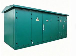
Ground-mounted PAD-type transformers offer high versatility, low cost, and easy installation, making them suitable for distributed deployment in large-scale ground-mounted photovoltaic arrays. Skid-mounted integrated units are prefabricated and commissioned at the factory, allowing for immediate on-site operation; they are suitable for remote mountainous areas, temporary projects, and scenarios with tight construction schedules. Containerized integrated substations combine transformation, switching, protection, and monitoring systems; they have an extremely small footprint and high levels of intelligence, making them suitable for key projects with limited space. Compact dry-type equipment features a neat appearance, low noise, and fire resistance, and is commonly used on commercial and industrial rooftops and within factory premises.
Scientific Selection of Cooling Methods
ONAN natural oil cooling features a simple structure, low energy consumption, and low O&M costs, making it suitable for IDT equipment in array areas with conventional climates and offering the best cost-performance ratio. ONAF forced air cooling enhances heat dissipation capacity by 20%–30%, making it suitable for high-temperature regions, high-capacity main transformers, and full-load operating conditions; the automatic start-stop function of the fans balances performance and energy consumption. Dry-type air cooling produces zero oil contamination, offers fire safety, is environmentally friendly, and operates quietly; it is suitable for indoor, rooftop, and high-occupancy environments, requiring only appropriate derating in extremely high-temperature conditions.
Key Technical Specifications to Consider
Basic Electrical Parameters
The rated capacity is calculated based on the total power of the inverters, with a 10%–15% overload margin reserved, to strictly control the increase in no-load losses caused by excessive oversizing. The project primarily adopts the Dyn11 vector group, which offers excellent harmonic suppression and ground fault protection capabilities. Short-circuit impedance is set at an appropriate value to balance fault protection and voltage stability; large grid-connected main transformers are prioritized for OLTC (On-Line Tap Changer) configuration to accommodate fluctuations in PV power and grid voltage, thereby meeting grid-connection voltage regulation requirements.
Insulation and Temperature Rise Parameters
Since PV equipment is subjected to long-term harmonic heating and high ambient temperatures, Class F and Class H high-insulation materials are prioritized for their superior heat resistance and anti-aging properties. Oil-immersed transformers feature a 55/65°C low-temperature-rise design, while dry-type windings maintain a temperature rise below 100°C; lower temperature rises effectively reduce losses and extend the equipment’s service life by 25 years.
Protection and Weather Resistance Parameters
Standard outdoor equipment starts at IP54; for extreme environments such as dusty or coastal areas, protection is upgraded to IP65 fully sealed protection. Standard outdoor units use electrostatic powder coating for corrosion protection; coastal salt fog environments employ stainless steel enclosures combined with heavy-duty Marine coatings; and desert environments utilize wear-resistant, erosion-resistant structures—ensuring comprehensive protection for long-term, stable outdoor operation.
Energy Efficiency and PV-Specific Parameters
Low-loss cores and optimized winding designs are prioritized to balance full-load and partial-load efficiency, adapting to the intermittent power output characteristics of photovoltaic systems. IDT transformers must meet the K9–K20 high harmonic resistance rating to withstand high-frequency harmonics from inverters, thereby preventing overheating, resonance, and excessive losses. Equipment noise levels near residential areas are controlled below 55 dB, while short-circuit withstand capacity is rigorously verified to ensure the transformer can withstand fault current surges from the power grid and inverters.
Intelligent Supporting Configuration
Standard safety features include online oil temperature and oil level monitoring, gas protection, pressure relief, and surge protection, providing real-time early warnings of potential faults. A SCADA communication interface is provided to support remote monitoring, data acquisition, and fault alarms, enabling unmanned operation and maintenance for smart photovoltaic power plants.
Common Challenges in Solar Power Transformer Projects
Inverter Harmonic Interference Issues
The PWM modulation of inverters generates a large amount of high-frequency harmonics, which is the primary cause of photovoltaic transformer failures. Conventional transformers cannot withstand harmonic surges; prolonged operation can lead to core overheating, insulation aging, grid-connection tripping, or even burnout. EPC procurement must strictly avoid the use of standard distribution transformers as substitutes throughout the entire process. Instead, specify dedicated IDT models rated K9 or higher for harmonic resistance, which feature built-in electrostatic shielding and optimized winding structures. For large-scale projects, conduct harmonic simulation and mitigation design in advance to eliminate harmonic risks at the source.
Frequent Load Fluctuations Accelerate Equipment Aging
PV power generation fluctuates in real time with sunlight, causing transformers to undergo repeated thermal cycling over the long term, which can lead to loose windings, cracked insulation, and reduced service life. When selecting models, choose types optimized for variable PV loads, ensure sufficient thermal margin, improve efficiency during low-load operation, precisely match capacity to eliminate excessive redundancy, and pair them with forced air-cooling systems to respond quickly to load changes.
Risk of Failures in Extreme Environments
High temperatures, dust, salt fog, and high altitudes can easily cause heat dissipation blockages, insulation failure, and enclosure corrosion. EPC contractors must perform customized parameter upgrades based on the project’s location, specifically enhancing insulation, protection, corrosion resistance, and heat dissipation configurations to avoid frequent failures later on caused by using generic models in specialized environments.
Challenges in Transporting Oversized Equipment
Large main transformers are bulky and heavy, and road access limitations in remote locations can easily cause project delays. During the initial procurement phase, prioritize modular, skid-mounted, or split-type designs; complete route surveys and logistics planning in advance; and select suppliers with experience in transporting oversized equipment to ensure smooth delivery and on-site installation.
Grid Connection Compliance Risks
Power grids in various regions have strict regulations regarding voltage regulation, reactive power support, fault ride-through, and harmonic limits; failure to meet these parameters will result in immediate rejection of grid connection. The EPC contractor must coordinate with the power grid in advance to confirm technical standards, incorporate grid connection requirements into procurement specifications, prioritize models with on-load tap changers and high power quality, and complete system simulation calculations ahead of schedule to ensure full compliance of the equipment.
Uncontrolled Long-Term O&M Costs
Low-cost, unbranded equipment tends to have high failure rates, scarce spare parts, and exorbitant O&M costs. EPC procurement must move away from a “lowest-price” mindset and prioritize standardized, highly versatile equipment with comprehensive after-sales support. By integrating online monitoring to enable predictive maintenance and relying on long-term after-sales support from reputable manufacturers, EPCs can reduce total lifecycle O&M costs.
Integrated Transformer Solutions for Different Solar Applications
Large-Scale Ground-Mounted PV Power Plant Solution
This integrated solution employs a “distributed multi-winding IDT + central main transformer + modular substation” configuration. It features decentralized step-up and collection within the array area to reduce line losses, while the step-up station’s high-capacity main transformer enables centralized grid connection. Equipped with dual-mode cooling, on-load voltage regulation, intelligent monitoring, and redundant design, the system is adapted to extreme outdoor environments and stringent grid connection standards, enabling efficient power generation, stable grid connection, and unmanned operation and maintenance.
Commercial and Industrial Distributed PV Solution
Primarily utilizing compact PAD-type and dry-type transformers, this solution leverages the advantages of low noise, fire resistance, small footprint, and quick installation to suit rooftops, confined spaces within industrial sites, and high-traffic areas. Small-capacity transformers at multiple locations are precisely matched to string inverters, eliminating equipment redundancy and ensuring normal production operations are not disrupted. Installation cycles are short, and O&M is convenient.
PV + Energy Storage Hybrid Power Plant Solution
PV-storage projects involve bidirectional power flow and frequent charging/discharging cycles, resulting in more complex operating conditions. Specialized bidirectional-compatible transformers must be selected, with optimized winding and insulation structures to withstand bidirectional harmonics and thermal shocks, ensuring stable operation without derating. Equipment is designed with expansion capacity to accommodate future energy storage upgrades, enhancing the power plant’s peak-shaving and frequency regulation capabilities as well as system stability.
Advantages of the Integrated Solution
Integrated prefabricated substations are factory-assembled and commissioned with transformers, switches, protection systems, and monitoring systems. On-site installation requires only wiring and commissioning, significantly shortening construction time and reducing civil engineering and construction costs. With strong compatibility, a high degree of standardization, convenient operation and maintenance, and flexible scalability, this solution is the mainstream choice for large and medium-sized PV projects.。
International Standards and Certifications
When procuring equipment for overseas PV EPC projects, compliance is a core prerequisite for customs clearance, grid connection acceptance, and project implementation. Since transformer standards, mandatory certifications, and grid connection regulations vary significantly across different countries and regions, EPC contractors must clarify internationally recognized standards and regional compliance requirements in advance, strictly control equipment qualifications and factory testing, and mitigate project risks such as acceptance failures and customs clearance delays.
Core International Industry Standards
There are two mainstream, authoritative standard systems for global PV transformers, each tailored to different overseas regional markets, serving as the core basis for equipment design, testing, and acceptance:
IEC 60076 Series Standards: These are globally applicable general standards for power transformers, focusing on core requirements such as equipment load adaptability, loss limits, insulation specifications, and weather resistance under renewable energy operating conditions. They serve as the foundational market access standards for PV equipment in the vast majority of overseas regions.
IEEE C57 Series Standards: These are the core standards specific to the North American market. They define design specifications, manufacturing processes, and testing standards for PV-specific transformers, with particular emphasis on detailed testing requirements for the harmonic K-factor, tailored to the grid-connection operating conditions of North American PV projects.
Mandatory Certifications and Grid-Connection Regulations in Overseas Regions
Each overseas region has its own mandatory certifications and technical requirements for grid connection. Equipment that does not meet these standards cannot be successfully connected to the grid and put into operation; therefore, EPC cross-border procurement must strictly comply with these requirements:
European Union (EU): Equipment must obtain CE certification, strictly comply with the Low Voltage Directive (LVD) and the Electromagnetic Compatibility (EMC) Directive, and meet the environmental compliance requirements of RoHS and REACH.
North America: Equipment must pass UL safety certification and strictly comply with the IEEE 1547 grid-connection technical specifications to ensure safe operation and grid compatibility.
United Kingdom: Project equipment must comply with the G99 grid connection standard and meet the local grid’s specific requirements for power quality, equipment protection, and fault ride-through.
To ensure project compliance, EPC contractors must strictly control the factory acceptance testing (FAT) process, completing routine performance tests and specialized type tests. They may commission a third-party organization to conduct witnessed FAT acceptance inspections and ensure that complete test reports and compliance certificates are provided, thereby mitigating risks such as grid connection failures and customs clearance delays at the source.
How to Choose the Right Transformer Manufacturer
When procuring photovoltaic transformers, low price alone should not be the sole criterion for evaluation. EPC contractors must establish a multidimensional, standardized supplier screening and evaluation system to control equipment quality, delivery capabilities, and after-sales support from the source, thereby mitigating project quality risks and potential operational and maintenance issues down the line. High-quality suppliers must fully meet standards across five key dimensions—technical capabilities, production quality control, testing capabilities, supporting services, and delivery capabilities—while using total life-cycle cost as the ultimate basis for procurement decisions. The specific screening criteria are as follows:
Technical Capability Assessment: Priority should be given to manufacturers with deep expertise in the PV and PV-storage sectors and extensive experience in completed projects both domestically and internationally. High-quality manufacturers can provide a full suite of technical support, including harmonic simulation, thermal simulation, parameter customization, and grid-connection technical integration. They should be able to accommodate personalized design requirements tailored to different site conditions and regional grid-connection standards, thereby providing technical support for compliant grid connection and stable project operation.
Production Quality Control Assessment: Reputable manufacturers must hold certifications for the three major management systems: ISO 9001 (Quality Management), ISO 14001 (Environmental Management), and ISO 45001 (Occupational Health and Safety). Relying on automated production lines and standardized processes, combined with mechanisms for random incoming material inspections, in-process inspections, and 100% finished product inspections throughout the entire production cycle, they ensure consistent equipment parameters and stable performance, effectively eliminating batch-level quality defects.
Testing and Inspection Capability Assessment: Prioritize original manufacturers equipped with independent, specialized laboratories capable of independently conducting a full suite of type tests, specialized PV performance tests, and harmonic immunity testing. Through a comprehensive factory acceptance testing process, ensure that equipment parameters genuinely meet standards, eliminate industry issues such as falsified specifications and the substitution of inferior products for superior ones, and guarantee the equipment’s suitability for the specific operating conditions of PV systems.
Full-Cycle Service Capability Assessment: High-quality suppliers provide one-stop, end-to-end services covering preliminary solution optimization, drawing coordination, parameter customization, on-site installation and commissioning, fault response, lifetime technical support, and original manufacturer spare parts supply, comprehensively ensuring project implementation and long-term stable operation and maintenance.
Delivery and Performance Capability Assessment: Manufacturers must have sufficient production capacity and stable production cycles to ensure on-time project delivery. For cross-border projects, they must possess proven expertise in customs clearance, logistics, overseas delivery, and overseas after-sales service to fully meet the performance requirements of both domestic and overseas PV projects.
Conclusion
The procurement of photovoltaic transformers is a systematic process that determines the quality, grid-connection compliance, and long-term returns of an EPC project. Precise selection, compliant specifications, high-quality equipment, and reliable suppliers are key to the successful implementation of the project. EPC teams must adhere to five core principles—scenario adaptation, compliance first, energy efficiency as the top priority, full-lifecycle cost reduction, and vendor empowerment—to establish a standardized and refined procurement and selection system. By addressing these factors from the outset, they can prevent equipment failures, grid connection issues, power generation losses, and O&M cost overruns, thereby comprehensively enhancing the quality of PV project construction, operational stability, and long-term return on investment.