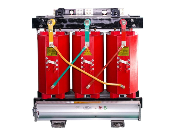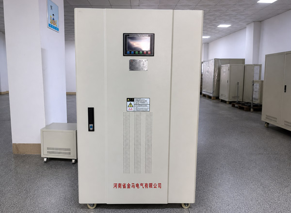


Power transformers are one of the most valuable and critical assets in transmission and distribution networks. A large transformer failure may lead to large-scale power outages, huge maintenance costs, and even serious safety accidents. Scientific power transformer testing can expose problems before insulation aging, winding defects, core failure or oil pollution turn into catastrophic accidents.
This guide will systematically explain the core contents of power transformer testing: test types and standards, preparation before testing, step-by-step operation process, detailed explanation of common methods, interpretation of results, common errors and suggestions for testing frequency.
What is power transformer testing?
Power transformer testing refers to a set of standardized diagnostic procedures for transformers, covering electrical, mechanical, thermal and chemical dimensions, to verify design integrity, manufacturing quality, insulation status, performance parameters and overall health.
This system mainly follows IEC 60076 Series(especially the general requirements of IEC 60076-1) and IEEE C57 Series(e. g. C57.12.90 test procedures, C57.152 field diagnostic guidelines) standards.
Power transformers are subjected to multiple stresses such as electrical load, thermal cycling, moisture intrusion, short-circuit power and natural aging for a long time. The core value of testing is “early detection and early treatment”-capturing degradation signals months or even years before a failure occurs, providing a basis for maintenance decisions and minimizing unplanned power outages.
Main types of power transformer testing
According to IEC 60076 and IEEE related guidelines, transformer testing is divided into 3 categories.
Routine Tests (Routine Tests)
Routine Test Pair each one transformers must be carried out before they leave the factory to confirm the manufacturing quality and basic performance of the product. Typical items include: winding resistance, voltage ratio and phase shift, insulation resistance, no-load loss and no-load current, load loss and short-circuit impedance, dielectric test (applied/induced withstand voltage) and insulating oil test.
Routine tests are not exempt and are included in the price quoted for each power transformer equipment.
Type Tests
The type test is only designed for a 1 transformer. One representative product to prove that the design itself meets the performance requirements. Common items are temperature rise test, lightning impulse, operation impulse, short circuit tolerance and sound level measurement. After the design is passed, the subsequent products with the same design can refer to the existing report without repeating the test.
Special Tests (Special Tests)
Special tests are only carried out when explicitly requested by the user and are used for additional verification of specific scenarios, such as zero sequence impedance, partial discharge, harmonic testing, etc.
Four testing phases of the full life cycle
Factory Acceptance Test (FAT): Complete all routine tests and applicable power transformer types/special tests before shipment, and customers are often present to witness.
On-site pre-commissioning test: Verify whether there is any damage during transportation and whether the assembly is correct, usually including transformation ratio, winding resistance, insulation resistance, dielectric loss and oil quality test.
In-flight periodic testing DGA, dielectric loss, insulation resistance and appearance inspection are carried out according to the cycle. DGA is usually carried out once a year for large equipment.
Post-Fault Diagnostic Test: Carry out targeted special diagnosis after the power transformer experiences short-circuit trip, abnormal sound or protection action.
Preparation Before Testing a Power Transformer
Adequate preparation is a prerequisite for testing safety and data accuracy. Transformer testing involves high voltage, energy storage components and core remanence, any leakage may cause personal injury or equipment damage.
Safety First: Isolation, Verification, and Control
The first step is to completely isolate the power transformer from all power sources, including the high and low voltage sides, the neutral point, the auxiliary power supply and all possible reverse power transmission paths. Subsequently perform a formal LOCK-Out Tag-Out (LOTO) procedures to prevent accidental power transmission, and notify the dispatch room, for work permits.
Electricity inspection must use an electroscope of appropriate voltage level, and perform “live-no-live” verification on all terminals. It should be noted that nearby charged equipment may induce voltage through capacitive coupling, and it cannot be assumed that the terminal has no power only by “power failure.
After confirming that there is no voltage, fully discharge the residual energy storage of the winding and install a temporary grounding wire. Fences and warning signs shall be set up on the site, and the operators shall wear PPE (anti-arc suit, insulating gloves, protective glasses, safety helmet, etc.) matching the risk level.
Special reminder: never test a transformer in a vacuum the dielectric strength of insulating oil decreased significantly under vacuum. Before the test, you must confirm that the tank is at atmospheric pressure or filled with oil as required.
Documentation and Planning Review
Before starting work, collect nameplate parameters and factory test report (this is the most important part of field test baseline Baseline), drawings, history records and transportation storage records, clear test purpose, acceptance criteria and applicable standards.
Before the electrical test, a systematic appearance and mechanical inspection must be completed: whether the oil tank has oil leakage, bulging, overheating and discoloration; Whether the oil level of each oil conservator is normal; The cleanliness of silicone respirator, valve position and casing; Whether the grounding, cooling system, gas relay, pressure release device and other accessories are in good condition.
When problems such as low oil level and dirty casing are found, the electrical test shall be carried out after treatment.
Environment and Equipment Preparation
The site should be clean, dry and ventilated, and the ambient temperature and humidity should be recorded (temperature correction is required for resistance and insulation readings). All instruments must match the range and voltage level of the device under test within the validity period of calibration.
Before wiring, short-circuit the secondary side of the built-in CT to ground, and clearly mark all terminals and tap positions. Also in advance planning: DC current is used for winding resistance test, and remanence will remain in the iron core after the test. If AC tests (excitation current, SFRA, transformation ratio, etc.) are to be carried out subsequently, arrangements must be made. demagnetization link.
How to Test Power Transformer Step by Step
The following is a set of general test procedures for field delivery and maintenance scenarios. In actual operation, please adjust according to the specific conditions of the equipment (voltage level, capacity, oil-immersed transformer or dry type transformer), applicable standards and manufacturer’s instructions.
Step 1: Check the transformer technical data
First, collect and check all relevant documents: nameplate parameters, factory test reports, drawings, historical test records, operation resumes and transportation and storage records.
Clarify the test items, acceptance criteria and applicable standards to be carried out this time, and formulate a detailed test plan. At the same time, the ambient temperature and humidity are recorded to prepare for subsequent temperature correction.
Step 2: Isolate the Transformer and Establish Safe Working Conditions
Complete power-off isolation, LOTO lock-out and tag-out, power check, discharge and temporary grounding as described above. Arrange operation fence and wear personal protective equipment.
It must be emphasized repeatedly: if there is any doubt about the isolation status or zero voltage verification, stop the work immediately and find out the cause before continuing. Safety always takes precedence over duration.
Step 3: Appearance and mechanical inspection
Systematic visual inspection of power transformer equipment and all accessories, including oil tanks, oil levels, bushings, valves, grounding, cooling systems and various protective accessories.
Record the anomalies found one by one. Any problems that can be handled on site (such as oil replenishment, casing cleaning, valve adjustment) should be completed before the start of electrical testing.
Step 4: Carry out basic electrical tests
Basic electrical test is the core of the vast majority of power transformer test projects, usually in accordance with the “first change ratio, after resistance, first low voltage, after high voltage” logic sequence. Make sure that the equipment is still isolated and grounded each time you change the wiring.
Variable Ratio and Coupling Group Test (TTR): Verify each phase change ratio at the relevant tap position and confirm that the polarity and phase group are consistent with the nameplate.
Winding DC resistance test: The four-wire (Kelvin) connection is preferred, measuring phase by phase and winding by winding, and correcting the result to the standard reference temperature (usually 75°C).
Insulation resistance and polarization index (PI) test: Measure the insulation resistance between each winding and to ground, and record the readings for 1 minute and 10 minutes.
Excitation current test: Measure the no-load excitation current and loss under reduced voltage to judge the condition of the iron core.
Dielectric loss (tan δ) test: Evaluate the overall state of the winding and bushing insulation, usually measuring the capacitance at the same time.
For oil-immersed power transformers, oil sample collection shall be arranged at the same time of electrical test and submitted for inspection as soon as possible.
Step 5: Carry out advanced diagnostic tests as needed
Depending on the purpose of the test, the importance of the equipment and the results of the basic tests, further diagnostic items are selected: load loss and impedance test, no-load loss test, frequency response analysis (SFRA), partial discharge measurement, core and clamp insulation resistance, magnetic balance test, and functional check of the cooling system and protection relay.
For large power transformers with capacities greater than 5 MVA or critical-field equipment, a more complete test portfolio is often required. All advanced tests shall follow the recommended sequence to avoid mutual interference.
Step 6: Analyze the results against the acceptance criteria
All measurements are itemized against nameplate data, factory report baselines, historical records, and standard limits. Items requiring temperature correction must be corrected before comparison.
The analysis focuses on 3 aspects: interphase consistency, the magnitude of deviation from the baseline, and historical trends. When out-of-tolerance results (such as ratio deviation exceeding ± 0.5, high dielectric loss, abnormal DGA gas, low insulation resistance or unbalance between phases) are found, the cause must be found out and retested for confirmation.
Step 7: Organize records and determine follow-up actions
Complete recording of all readings, environmental conditions, instrument numbers, tap locations, test dates and operator information, issuance of formal test reports, and identification of equipment status conclusions.
If the equipment is qualified, the last round of inspection shall be completed before putting into operation: remove all temporary grounding wires and test leads, restore wiring, confirm oil level and valve status, check the protection setting value, and put into operation only after obtaining the official power transmission license.
The specification documentation will be the most valuable condition baseline for the entire service life of this transformer.
Commonly used transformer test Method
Transformation Ratio Test (TTR): Verify the transformer ratio, polarity and connection group. It is very sensitive to inter-turn short circuit, wiring error and tap changer failure. It should be carried out under multiple tap positions.
Winding DC resistance test: Inject DC current into the winding, and calculate the resistance through the voltage drop (use the four-wire system to eliminate the influence of the lead wire), and you can find loose connections, broken strands, poor welding or tap contact problems. Large equipment readings take several minutes to stabilize, be sure to wait for stability before recording.
Insulation resistance and polarization index: Apply DC high voltage (usually 1-5 kV) to measure the insulation resistance between windings and to ground. PI = 10 minute value ÷ 1 minute value: ≥ 2.0 is excellent; 1.5-2.0 should be paid attention to;<1.5 strongly indicates moisture or pollution.
Dielectric loss (tan δ): Measuring the dielectric loss angle of an insulation system is highly sensitive to insulation aging, moisture and pollution, often capturing degradation trends long before failure, usually measuring capacitance at the same time.
No-load and load loss test no-load test measures iron loss and no-load current; Load test (one side short circuit, applied reduced voltage) measures copper loss and short-circuit impedance. Significant changes in impedance may indicate winding deformation.
Dielectric withstand test: External withstand voltage and induction withstand voltage are applied to verify the ability of insulation to withstand overvoltage; lightning impulse and operating impulse tests belong to the category of type tests.
Dissolved gas analysis in oil (DGA) oil-immersed transformer the most powerful diagnostic tool. Typical indications for each characteristic gas: hydrogen → partial discharge; methane/ethane → low and medium temperature overheating; ethylene → high temperature hot spot (>300°C); acetylene → arc (most dangerous);CO/CO → insulation paper aging. Interpretation combines the three-ratio method and Duval triangle, focusing on absolute content, growth rate and mutual proportion.
Frequency Response Analysis (SFRA): The injection sweep signal is compared with the response curve change, and the mechanical displacement of the winding or iron core is detected. It is highly sensitive to the deformation caused by the transportation impact and short-circuit electric force.
How to Interpret Power Transformer Test Results
The core of the test data interpretation is the “3 comparison”: comparison with the nameplate, comparison with the factory baseline, and comparison with historical data. Trends and interphase consistency are often more revealing than single absolute values.
Transformation ratio: The deviation shall be within ± 0.5, and the three phases and all gears shall be consistent. A 1 phase out-of-tolerance indicates inter-turn short circuit or tap fault, and serious out-of-tolerance shall not be put into operation.
Winding resistance: After temperature correction, the phase difference is controlled within 1-2%. A high 1 phase usually means a loose connection, broken strand or poor contact.
Insulation resistance/PI: In addition to the PI value, the continuous downward trend of insulation resistance is more indicative of deterioration than a single low value.
Dielectric loss: After 20°C correction, new equipment is usually less than 0.5%, and equipment in operation is generally acceptable below 1.0%. The increase of 1.5-2 times over the baseline should be highly concerned.
Excitation current: The three phases should be basically balanced and close to the baseline. The abnormally high level of a certain phase indicates inter-turn short circuit or iron core problem, and attention should also be paid to remanence interference.
DGA: According to IEEE C57.104 or IEC 60599, the equipment status is divided into four levels: normal, caution, abnormal and dangerous. Continued acetylene growth usually requires an immediate blackout check.
10 Common Mistakes in Testing Power Transformer
- Inadequate isolation, discharge or grounding.Breaking the circuit breaker alone is safe by default and may result in electric shock or instrument damage. LOTO, electrical inspection, discharge and grounding must be performed completely.
- Ignore demagnetization after DC test.Remanence will distort the AC test results, and may also generate huge inrush current during operation, resulting in protection misoperation.
- Skip temperature correction.The copper resistance changes by about 0.4 per 1°C, and uncorrected comparisons are bound to go wrong.
- The wiring is not standard.Using a two-wire system to measure micro-ohm-level resistance and the variable ratio test lead to reverse connection will get completely wrong readings.
- Record if the reading is not stable. Unstable current of power transformer or improper selection of test current will introduce errors.
- Ignore the tap position.Many “exceedances” are simply a mismatch between the tap position and the reference.
- Incomplete documentation.To remember only values without conditions and trends is to give up the most valuable diagnostic clues.
- The environment or state is not suitable.Rainy days to measure insulation, the instrument is not calibrated, vacuum pressure, will bring risks.
- Test order confusion.Should follow the “first visual, then isolation, then electrical, final diagnosis” logic.
- To draw conclusions based on a single result.The health judgment must be based on the cross confirmation of TTR, winding resistance, insulation/PI, dielectric loss, excitation current and DGA.
How Often Should Power Transformer Be Tested?
There is no unified answer to the test cycle of power transformers. Equipment capacity, voltage level, load importance, age, operating conditions and manufacturer’s recommendations should be comprehensively considered.
| Test Item | Recommended cycle | Description |
| Appearance and basic operation inspection | Monthly to quarterly | Lowest Cost 1 Line of Defense |
| infrared thermal imaging | Once a year | Found connections, bushings, radiator hot spots |
| DGA and oil quality test | Annually; every 6 months for critical equipment | The cornerstone of oil-immersed equipment condition-based maintenance. |
| Complete set of off-line electrical tests | industry every 3 years; grid every 5 years | Important high-voltage equipment shall be encrypted. |
| Advanced diagnostics (SFRA, furfural, etc.) | Every 3-6 years or on demand | Often triggered by abnormal results |
| Protection and function check | Every 1-6 years | Including relay, cooling control |
Key influencing factors: DGA can encrypt equipment that supplies power to important loads such as hospitals and data centers every 3-6 months; Old power transformer equipment that has been in operation for more than 20-25 years should shorten the interval; Large power transformers (>5-10 MVA or ≥ 115 kV) should implement more rigorous plans; High humidity, heavy pollution or frequent overload environments should also be encrypted.
Modern operation and maintenance is moving from a fixed cycle.
Condition Based Maintenance (CBM): Use DGA trends, online monitoring and historical data to dynamically adjust the plan, and arrange targeted tests immediately after the equipment experiences a short circuit, lightning strike or abnormal signal.
How Do Transformer Manufacturers Guarantee Product Quality?
A reliable power transformer, its quality assurance system from the design stage has begun, through the material, manufacturing, testing and after-sales service of the whole process. High-quality transformer manufacturers usually have a complete quality assurance system in accordance with ISO 9001 and are fully aligned with product standards such as IEC 60076 and IEEE C57.
Design and Engineering Control: power transformer manufacturers use advanced electromagnetic, thermal and mechanical simulation software to ensure that their products meet performance, efficiency and short-circuit tolerance requirements. The new design must pass the internal design review before it is put into production, and complete the type tests such as temperature rise, impact and short circuit tolerance on representative products.
Raw material control: the iron core adopts low-loss oriented silicon steel sheet, the winding uses high-purity copper or aluminum conductor, the insulation material strictly meets the heat resistance grade and dielectric requirements, and the insulation oil must pass the breakdown voltage, micro-water, acid value and other full set of incoming inspection. Each batch of transformer materials shall be fully inspected or sampled, and the whole process can be traced through the batch number/serial number.
Manufacturing process control link: The core stacking adopts precise step-by-step lapping process, the winding process is automatically controlled by numerical control equipment to control the tension and number of turns, the insulation treatment adopts vacuum drying or gas phase drying to completely remove moisture, and the oil-immersed product is also filled with oil under vacuum to remove air and moisture. Statistical process control (SPC) and online detection are widely used in key processes to eliminate deviations in the bud.
Test link: In addition to the routine tests required for each unit, power transformer manufacturers also embed intermediate checks (ratio, resistance, insulation resistance, etc.) during the assembly process and provide factory acceptance tests (FAT) that customers can witness. The test equipment is calibrated regularly, and the laboratory is mostly approved by ISO/IEC 17025.
Documentation and Continuous Improvement: Each power transformer has a complete material, process and test record file, and a detailed test report and material certificate are attached when leaving the factory. Non-conforming product management, root cause analysis and corrective and preventive action (CAPA) mechanisms drive continuous quality improvement, supplemented by regular internal audits, supplier audits and third-party surveillance audits.
FAQ About power transformer testing
Q: What is the most important test?
For oil-immersed transformers in transit, DGA is the most powerful and can detect internal hazards years in advance. The overall health assessment is based on a combination of insulation/dielectric loss plus transformation ratio tests. A complete assessment always relies on multiple test cross-validation.
Q: What is the difference between routine test and type test?
Routine tests are carried out on each product to ensure that “this one is no problem”; Type test verifies the design itself to ensure that “this design is no problem”, and the report can be referenced with subsequent products of the design.
Q: How to judge the unqualified insulation test?
The insulation resistance is significantly lower than the baseline, PI is lower than 1.5, or the dielectric loss exceeds the standard and shows an upward trend, all indicate moisture, pollution or aging.
Q: How long does the test take?
The basic field test is several hours to one day; the comprehensive maintenance is 1-2 days; the FAT of large equipment is generally 3-5 days, and the temperature rise test alone takes more than 8-24 hours.
Q: Can you test without power-off?
The vast majority of electrical tests must be powered off and isolated, but DGA online monitoring, infrared thermal imaging, local discharge online monitoring, casing online monitoring, etc. can be carried out online. Reasonable strategy is the combination of online monitoring and early warning + regular power outage physical examination.
Conclusion
Power transformer testing is a systematic project that runs through the entire life cycle of the equipment, combining rigid criteria with trend diagnosis to form the most solid line of defense for the safe operation of the power grid. No matter in the face of new power transformer equipment acceptance or old equipment evaluation, please remember: the more prepared, the more credible the results; The more complete the data, the clearer the trend; Multi-project cross-validation is always better than the arbitrary judgment of a single data.